I. Introduction
As the main electromechanical energy conversion device, DC motor is widely used in various industries. With the rapid development of computer electronics technology, the control method of the motor has also undergone tremendous changes, and the analog control method has been basically replaced by the digital control method. This system uses ATmega8 single-chip microcomputer as the core controller. It controls the turn-on and turn-off of MOSFET devices in H-bridge by PWM wave, turns DC voltage into voltage pulse train, controls the width or period of voltage pulse, and converts 26V DC into AC power. It is obtained by rectifying the boost to 180V through the transformer, and the PWM control technology is also used to control the speed of the DC motor.
Second, the system hardware design
(1) System working principle
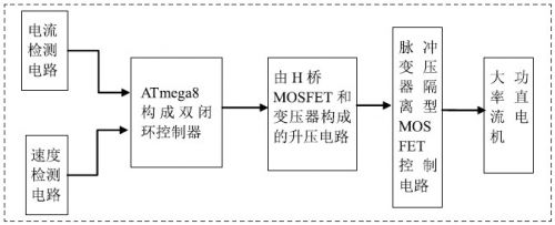
The system controller mainly uses the ATmega8 microcontroller as the control chip. The current is detected by the Hall sensor, and the photoelectric encoder detects the speed. The MOSFET is controlled by the PWM signal generated by the microcontroller, and the MOSFET is driven by a complementary isolated pulse transformer. Inverting direct current to alternating current is boosting the voltage of 26V to 180V through a transformer. For the control of the motor, we use a double closed loop speed control system.
(two) the main hardware design
1, double closed loop controller circuit
According to the principle of automatic control, the closed-loop system of feedback control is a system that is controlled according to the deviation of the adjusted amount. If the deviation is adjusted, the whole system will automatically generate the effect of correcting the deviation. In the design of this system, the proportional integral adjustment algorithm and the double closed-loop negative feedback system are used, which are current PI regulation and speed PI adjustment algorithm. The current loop output voltage value is calculated by the program, and the armature voltage value is used as the set value of the PWM waveform duty ratio, and the AVR single chip outputs the PWM waveform, in order to prevent the feedback control of the closed loop speed control system during the start and stall rotation of the armature current Too large a problem introduces a current cutoff negative feedback link. In order to get the input signal well, we added a Kalman filter using software programming. Kalman filtering is a best criterion for estimating the least mean square error, and seeks a set of recursive estimation algorithms. The basic idea is to use the state space model of signal and noise to make use of the estimated value and current time of the previous moment. The observations are used to update the estimate of the state variable and to estimate the time of occurrence.

Figure 1 High-power DC motor controller consisting of ATmega8
2, PWM shaping and MOSFET drive circuit
Using the characteristics of the 74HC74, the SD and RD of the U1002 can be connected to a high level, and the PWM signal is connected to the CLICK terminal. When the PWM is at a high level, since the D terminal of the 74HC74 is connected to the Q non-terminal, the output waveforms of Q and Q are alternately converted when the PWM transitions from low to high, thereby dividing the PWM of one channel into Two-way PWM. The two square wave signals are respectively connected to the input terminals of two NAND gates, and the PWM signals generated by the single chip are connected after the other two ports of the NAND gate are connected. When the PWM is low level, the two NAND gates are connected. The output is high, so that the last four PWM outputs are low, completing the dead band function of the driving MOSFET. When CLICK is on the rising edge, the Q and Q non-terminal outputs also alternately output high and low levels. Thus, the lower frequency PWM signal is transmitted through the 500 Hz carrier signal through the pulse transformer. 

ZTTEK Batteries, For 5G backup base station .Customize the lithium ion battery packs according to the application and product requirements of the customers.
Lithium ion battery integration requires a special set of skill and expertise to optimize the performance and battery life.ZTTEK Batteries , using the most advanced technology delivers the best quality battery packs.
Our batteries are safe to use, better performance, higher shelf life and a very low maintenance cost.
48V100Ah Lithium Ion Battery,Lithium-Ion Battery For Home Backup Electricity,Lithium Ion Battery 48V 100Ah,48V Lithium Iron Phosphate Battery
Jiangsu Zhitai New Energy Technology Co.,Ltd , https://www.zhitainewenergy.com
