At present, the demand for meat foods and dairy products is increasing: at the same time, people are paying more and more attention to the reliability of these products, which poses a new challenge for some enterprises, requiring enterprises to have a complete The management system strictly supervises and controls the production and processing of these products. However, in the past decade or more, animal outbreaks around the world have been erupting, such as mad cow disease, Streptococcus suis, foot-and-mouth disease, bird flu, etc., which pose a serious threat to the health and life of the people and also severely hit the world's livestock. Industry has attracted the attention of all countries in the world. To this end, governments have quickly formulated corresponding policies and adopted various measures to strengthen the monitoring and management of animals. Among them, the identification and tracking of animals has become one of these major measures. For example, the British government has to provide various means of tracking and identification for animals such as pigs, horses, cattle, sheep and goats.
The purpose of this system research is to use RFID (Radio Frequency IdenTIficaTIon) technology to establish a complete, flexible and convenient management system to improve the modern management level of pig farms. At the same time, it is convenient for managers when there are problems with pork and its products. Find the source of the disease and deal with it accordingly to avoid the loss. RFID is a non-contact automatic identification technology, which has the characteristics of large data storage, readable and writable, strong penetrating power, long reading and writing distance, fast reading speed, long service life and good environmental adaptability. And it is the only automatic recognition technology that can achieve multi-target recognition.
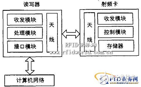
1 system structure and working principleThe RFID-based animal identification and tracking management system consists of three parts: RFID radio frequency card, reader/writer and computer network, as shown in Figure 1. The reader is generally used as a computer terminal to implement data reading and writing and storage of the RFID radio frequency card. It is composed of a control unit, a high frequency communication module and an antenna. The readers in this system include both fixed and handheld. The RFID card is a passive transponder. It is mainly composed of an integrated circuit (1C) chip and its external antenna. The RFID chip usually integrates RF front-end, logic control, memory and other circuits, and some even integrate the antenna together. On the same chip.

Figure 1 RFID-based animal identification system structure
The basic working principle of the system is: when a pig with a "ear stud" (RFID card) enters the RF field of the reader, the induced current obtained by the antenna is boosted by the booster circuit and used as the power source of the chip. The inductive current with information is detected by the RF front-end circuit and sent to the logic control circuit for information processing; the required recovery information is retrieved from the memory and sent back to the RF front-end circuit via the logic control circuit, and finally sent back to the reading through the antenna. Writer.
The computer network obtains the information of the pigs in the farm through the interface, and integrates the basic functions required for the daily management of the pig farm. The various records, statistics, reports, etc. involved in the daily management of the pig farm are all manually completed. Implement computer management. The system basically meets the needs of the current production management of pig farms, and provides information from macro decision-making, which is convenient for managers to understand the management status of pig farms in a timely and accurate manner and improve the modern management level.
2 system hardware designThe implementation of the hardware circuit in the system includes: the installation of the pig "ear stud" (RFID card), the implementation of the tag reader and the three parts of the computer network.
2.1 "Attachment" (RFID card) installation
At present, the basic methods for installing electronic labels for animals are collar type, ear tag (nail) type, injection type and pill type electronic label. Each label has its own characteristics and scope of application. The cost of the collar label is too high, and the injectable label and the pill label are not suitable for the pig, so the system uses a "stud" type electronic label. Stud-type electronic tags not only store more data, but also resist dirt and rain. The information stored in the "ear stud" type RF card includes: the address of the pig farm in the township, the postal code, the variety information, the date of wearing the earring, the quarantine and immune information, the disease information, the genealogy and reproduction information, the date of the release, etc. This information must cover the entire life cycle of the pig from birth to facilitate identification, tracking and management of the pig.
2.2 RFID tag reader implementation
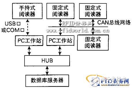
There are two types of RFID tag readers used in this system: one is a fixed reader; the other is a hand-held reader, see Figure 2. The main difference between the fixed reader and the handheld reader is that the handheld reader can input the information to the system software platform through the USB interface or COM port of the PC after reading a large amount of RFID tag information. in. The fixed reader is transmitted to the software platform in real time after reading the RFID tag information, and is not stored in the reader. The fixed reader is installed in a fixed position in the pig house, and data and information exchange can be performed in real time through the CAN bus network and the software platform. The handheld reader is very convenient to use, and the RFID tag information is read centrally before data exchange with the PC. Due to the limitation of space, only the principle block diagram of the fixed reader is given in this paper, as shown in Figure 3. The functions of each module are as follows:

Figure 2 System network structure diagram
Switching Residual Current Transformer
Switching Residual Current Transformer,Switching Transformer,Open Residual Current Transformer,Busbar Open Residual Current Transformer
Zibo Tongyue Electronics Co., Ltd , https://www.tongyueelectron.com
