1 Introduction
Embedded system refers to application-centered, computer-based, software and hardware tailoring, adapting to the application system's strict requirements for function, volume, cost, reliability, power consumption. The embedded system is application-oriented, and the hardware selection and software development mode of the system must be determined according to the specific application.
Permanent magnet brushless DC motor is one of the hotspots in the field of motor control research, which is closely related to its inherent technical advantages: electronic commutation replaces the mechanical commutation of brushed DC motor. Basically, it eliminates a series of problems such as sparks, noise, and high failure rate caused by brush commutation of ordinary brushed DC motors, and at the same time makes the performance of the system comparable to that of ordinary brushed DC motors. Applications. The electronic commutation of a permanent magnet brushless DC motor is inseparable from the rotor position signal of the motor. The traditional method is to detect the position signal by using a Hall device or other position sensor, which makes the maintenance and manufacture of the system inconvenient, and because of the sensor The unstable working characteristics bring some hidden dangers to the safe operation of the system. Therefore, the position sensorless solution has aroused great interest.
In this paper, the development of the sensorless permanent magnet brushless DC motor control system is combined with MICROChip's PIC18F452 microcontroller as the main control device, and the embedded real-time operating system μ C/OS-II is used as the software development platform. System development model and process.
2. System hardware platform design
The first step of embedded system design is to combine the specific application, comprehensively consider the system's requirements for cost, performance, scalability, development cycle, etc., determine the system's main control device, and use it as the core to build the system hardware platform. .
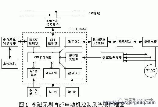
The key issue of the position sensorless permanent magnet brushless DC motor control system is position detection. A number of position detection schemes have been available, and the back EMF method has been widely adopted due to its simplicity and practicality. The principle of the back EMF method is: based on the three-phase voltage of the motor, the three-phase potential zero-crossing signal is obtained by hardware detection circuit or software algorithm, and then the phase of the commutation is obtained by software phase shift, and the commutation logic is completed at the commutation time. The commutation, triggering the inverter bridge to work with the appropriate conduction sequence, thus ensuring the normal operation of the motor.
The position sensorless control of permanent magnet brushless DC motor with back EMF method puts higher requirements on system hardware:
1 three external interrupt input pins to facilitate the capture of three opposite potential zero-crossing signals;
2 at least one PWM module to achieve chopper speed regulation of the motor;
3 Rich timer resources to complete software phase shifting, speed measurement and other functions;
4 multi-channel AD conversion module, capable of sampling speed and current and voltage signals of the main circuit;
5 hardware multiplier to ensure the speed and current regulator speed;
6 sufficient program and data memory for system expansion;
7 High-speed system operating frequency to ensure strong real-time performance of the system;
8 Rich communication modules to facilitate interconnection of systems with other embedded systems.
For the design of the position sensorless permanent magnet brushless DC motor control system, there are many special chips available, but in order to further improve the system performance and enhance the design flexibility, smart devices such as DSP or dedicated microcontroller are often used. However, this increases system performance while increasing system development costs. In order to design a high-performance, low-cost development platform, the requirements of the system hardware for the application, taking into account the high cost performance of the PIC18F452 microcontroller, select it as the main control device.
The PIC18F452 is an enhanced 8-bit microcontroller from Microchip. It is a reduced instruction set (RISC) design with a two-stage pipeline and a maximum operating frequency of 10 MIPS to meet the real-time requirements of the system. The instruction bus is 16 bits wide. The data bus is 8 bits wide; the MCU has 32K bytes of FLASH program memory, 1.5K bytes of data memory and 256 bytes of EEPROM for system expansion; it has 8 × 8 hardware multipliers; Provides 18 interrupt sources, two interrupt priority levels, and interrupt priority configurable. The PIC18F452 microcontroller is equipped with a wide range of peripheral modules that greatly simplify the design of the peripheral circuitry of the microcontroller. At the same time, Microchip provides a powerful instruction set for the PIC18F family of microcontrollers with a total of 77 instructions. Most of the instructions are single-word (2 bytes) memory, single-cycle execution, high compression ratio of application code, and instruction execution efficiency. high.
The hardware block diagram of the system composed of PIC18F452 as the main control device is shown as in Fig. 1.
It is worth noting that:
1 The commutation logic in the system is completed by the programmable logic device, mainly to improve the reliability of the system. From the functional point of view, it can be completely realized by the single chip microcomputer;
2 The speed detection of the motor can be calculated by software according to the position signal, so the speed sensor is omitted;
3 The analog input is the speed reference signal of the motor.
3. Embedded system software development model
For a simple application system, the software development mode of the system is usually shown in Figure 2, called the front-back system (also known as the infinite loop system).
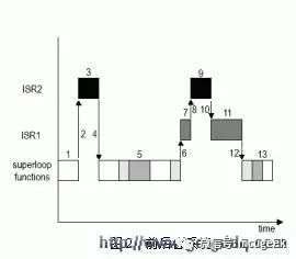
In the front and back system, the application is an infinite loop. The function is called in the loop to complete the corresponding operations. These operations are called background tasks; the interrupt service program handles asynchronous events, which is called foreground behavior. Because the information provided by the interrupt service routine is always processed until the background program runs to process the information, the worst case task response time is equal to the execution time of the entire loop. Because the execution cycle of the background loop is not constant, the application software development based on the front and back background mode, although the design process is simple, the real-time performance of the system is not guaranteed.
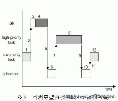
In order to improve the real-time performance of the system, a software development mode based on the embedded real-time operating system (RTOS) can be adopted. There are two types of RTOS: non-releasable kernels and deprivatable kernels. Commercially available are deprivable kernels, so this article only discusses such RTOSs. The kernel structure is shown in Figure 3.
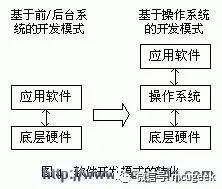
The RTOS subdivides the entire application into multiple tasks, each of which performs a specific function and is given a priority with its own task control block and stack space. Generally, each task is an infinite loop in the program structure, which has multiple states - sleep state, ready state, running state, suspended state, and interrupted state. The system kernel always makes the high-priority task in the ready state run first, and the interrupt service program can preempt the CPU. When the interrupt service program is completed, the system kernel makes the task with the highest priority in the ready state run (not necessarily the interrupted task). ). It can be seen that the RTOS-based software development model optimizes the system's task response time. More importantly, this development model transforms the functional-oriented application development into the application development of the surface task, which simplifies the logical structure of the system design. At the same time, because of the RTOS, the visibility of the application software to the underlying hardware is shielded. Converting the two-layer structure of the previous software system into a three-layer structure (as shown in Figure 4) greatly facilitates software expansion and hardware upgrade of the system.
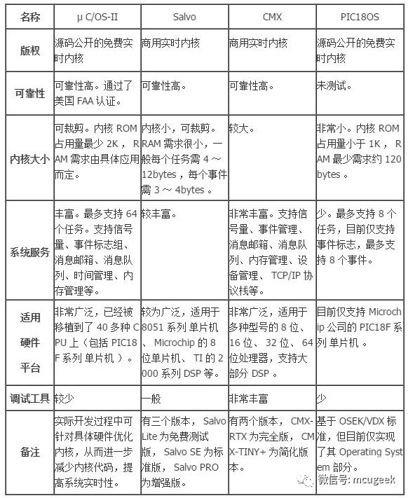
For PIC18F series MCUs, the commonly used embedded real-time operating systems are: μ C/OS-II, Salvo, CMX, PIC18OS, etc. They are all deprived real-time kernels, as detailed in Table 1.
Combined with the specific application of this paper, considering the system hardware resources and the characteristics of several real-time operating systems mentioned above, the operating system-based software development mode is selected, and μ C/OS-II is selected as the system software platform.
4. Application software development based on μ C/OS-II
μ C/OS-II is a portable, curable, tailorable and deprivable multi-tasking real-time kernel. Application development must first be completed on a specific hardware. μ C/OS-II has been fully portable in the process of writing. Most of its code is written in ANSI C. The processor-related code is concentrated in OS_CPU.H, OS_CPU_A.ASM, OS_CPU_C.C. In these three files, as long as these files are rewritten for specific hardware, the migration can be completed.
Table 1 Several embedded real-time operating systems for PIC18F series microcontrollers
Source: Radio and TV
MCU development gas station
Pay attention to the latest information and related technology applications of MCU development, exchange MCU innovation design experience, and go with MCU development talents!


Rotary Switch
Main band switch characteristics as below:
- Providing different rotation angles degree for options.
- Including multiple output digital coding modes.
- Including inhibit and parity signal to avoid error.
- Water and oil resistance. (IP65)
- Gold plating double contact points, stable contact resistance, long service life.
- Easy installation
Band Switch,Rotary Type Band Switch,Cnc Panel Band Switch,Rotary Band Switch
Feyvan Electronics Technology Co., Ltd. , https://www.fv-cable-assembly.com
