With the development of 3G technology, the system capacity is continuously improved, and the linearity requirements for the system are getting higher and higher. As the main nonlinear unit of the communication system, the performance of the power amplifier is crucial in the whole system. It is more and more difficult to simply use the power back-off method to meet the linear requirements, and it is difficult to meet the increasing efficiency requirements. As a result, many linearization techniques are continuously applied to the power amplifier design.
Commercially available linearization techniques include feedforward, DPD, and analog predistortion. The main disadvantage of the feedforward technology is that the error loop cannot simultaneously amplify the useful signal, resulting in very low efficiency. The main feature of the DPD technology is that the pre-distortion effect is achieved by processing the baseband signal, so the RF signal needs to be converted into a baseband first. After the signal is processed, it is restored to the RF signal and the output signal of the PA for synthesis, and the signal correction is completed. The biggest disadvantage is that the system is complicated, difficult to debug, and the effective bandwidth is limited. Compared with the above two linearization methods, the analog predistortion system has a simple structure, is easy to debug, and the efficiency can meet the demand, so it has become a popular linearization method.
However, the most important thing to simulate pre-distortion is to choose a suitable nonlinear device, its characteristics should be very close to LDMOS, in order to simulate the nonlinear characteristics of PA, and finally achieve the effect of pre-distortion. Such device selection requires a large amount of experimental data and verification, which brings great challenges to the previous research and development.
This paper adopts the new predistortion chip SC1887 integrated by Scintera, cooperates with NXP's BLF6G22LS-130, uses Doherty structure, and the former promotes the use of BLM6G22-30G, and finally completes WCDMA 30W power output, which provides a target for repeater customers. An efficient, energy-efficient solution for 20W machines.
SC1887 predistortion circuit compositionCompared with the traditional analog predistortion circuit, the SC1887 greatly simplifies the structure of the predistortion circuit and reduces the application of peripheral components, making the whole circuit more compact and easier to miniaturize; and further improving system reliability. The implementation principle is shown in Figure 1.
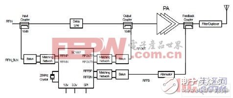
Figure 1 SC1887 predistortion implementation block diagram
The circuit adopts a closed-loop structure, and the cancellation effect is superior to the conventional open-loop structure. The chip can work normally from 600MHz to 2.8GHz by adjusting the matching between RFin, RFout and FFFB ports and each balun. This solution uses Murata's high-Q capacitors and low-loss inductors to control the three port echoes above 18dB (the board is a four-layer board designed using Isola's special board IS680). At the same time, it can be connected to the computer through SPI to monitor its working status at any time, making debugging easier and more efficient.
Specific implementationDXY Dingxin Lab uses NXP's high-performance LDMOS to independently design a practical Doherty structure, which is perfectly integrated with the analog predistortion chip SC1887. The pre-push in the RF solution uses NXP RFSS BGA6589, the driver stage uses NXP BLM6G22-30G, and the last stage uses NXP BLF6G22LS-130. Compared with other manufacturers in the industry, NXP's LDMOS has high efficiency and high gain, and it has an irreplaceable advantage in high efficiency and high power amplifier applications.
Among them, the BLF6G22LS-130 single tube gain can reach 17dB, the saturation efficiency is 55%, the gain after Doherty is also 15-16dB, and the final 6dB retraction efficiency is above 40%. BLM6G22-30G is a plastic integrated integrated secondary IC tube with a gain of up to 28dB and high efficiency. It is the first choice for high power boosting stage. At the same time, in order to improve the output power, Yantel High Frequency Technology Co., Ltd. introduced the low insertion loss bridge HC2100A03.
The SC1887 has a certain dynamic range requirement for the input signal strength of both RFin and RFFB ports. In order to better cooperate with the power amplifier, two ATT circuits are used in the loop to adjust the gain range of the main path and the feedback path in real time to ensure that the SC1887 performs well within a certain power output dynamic range. The specific implementation of the circuit principle is shown in Figure 2.

Figure 2 Power amplifier block diagram
Test result analysisThe test results are shown in Table 1. It can be seen from the test data that when Pout=44.7dBm, the ACPR after cancellation is above 52dBC, which can satisfy the 3GPP spectrum emission template. The efficiency can be 27%, which is more than 10% higher than the ordinary retreat power amplifier, which significantly reduces the energy consumption, far exceeding the operator's bidding requirements, and meets the development needs of today's energy saving, green and low carbon.
Table 1 WCDMA single carrier test results

By analyzing the above test results, it can be seen that the program has the following advantages:
1. High efficiency: Adopting Doherty plus analog predistortion linearization technology, the efficiency is at least 10% higher than that of ordinary HPA.
2. Low cost: The power amplifier tube plays a dominant role in the whole power amplifier cost. With the same power output, the solution reduces the usage by half and reduces the cost compared with the traditional HPA.
3. Simple structure, easy to debug: Simplifies the structure of the pre-distortion circuit, reduces the application of peripheral components, makes the whole circuit more compact, improves the reliability and consistency of the whole system, and facilitates production debugging.
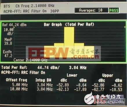
Figure 3 2140MHZ test results
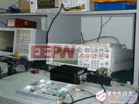
Figure 4 WCDMA30W PA solution test platform
Appendix: Nonlinear Distortion of Power Amplifiers and Implementation of Traditional Analog Predistortion
The nonlinear distortion characteristics of the power amplifier are mainly characterized by two characteristics of AM-AM distortion and AM-PM distortion, as shown in Fig. 5.
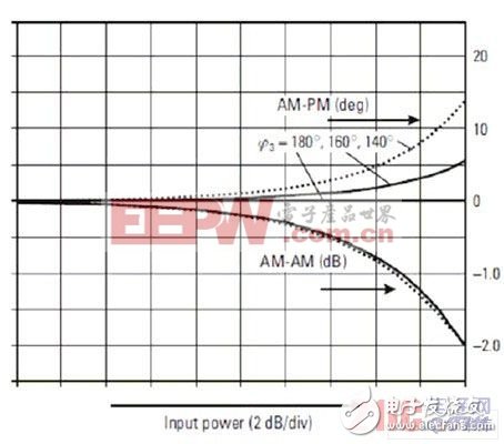
Figure 5 Schematic diagram of AM-AM and AM-PM characteristics of the power amplifier
For ease of analysis, we ignore the memory effect of the amplifier and identify the transmission characteristics of the amplifier as:
![]()
Among them, Vi(t) and Vo(t) are the input and output voltages of the power amplifier. Expand this formula with the Taylor series, take the first 3 terms, and get the formula (2):

To simplify the analysis process, we assume that the input is a point frequency signal, ie Vi=Acosω1t, then the output signal is:

It can be seen from Equation 3 that due to the nonlinearity of the power amplifier, the output signal contains not only the frequency components of the input signal, but also new DC components, second harmonics and third harmonic components. Where the amplitude of the fundamental component is ![]() Where k1 is the linear gain,
Where k1 is the linear gain, ![]() It is nonlinear distortion.
It is nonlinear distortion.
When k3》0, ![]() 》K1, the gain exhibits an expansion characteristic at this time; conversely, when k3 0,
》K1, the gain exhibits an expansion characteristic at this time; conversely, when k3 0, ![]() K1 , at which point the gain exhibits a compression characteristic. For most nonlinear devices (including LDMOS), k3 0, gain compression occurs as input power increases, which is AM-AM distortion. Some non-linear devices exhibit k3'0 gain expansion characteristics under certain bias conditions. The traditional predistorter is to find such a device to achieve pre-distortion.
K1 , at which point the gain exhibits a compression characteristic. For most nonlinear devices (including LDMOS), k3 0, gain compression occurs as input power increases, which is AM-AM distortion. Some non-linear devices exhibit k3'0 gain expansion characteristics under certain bias conditions. The traditional predistorter is to find such a device to achieve pre-distortion.
AM-PM distortion means that the phase of the output signal varies with the amplitude of the input signal. For an ideal amplifier, the phase of its output signal is independent of the amplitude of the input signal. However, in practical amplifiers, the amplitude modulation of the input signal results in phase modulation of the output signal, typically expressed in Bessel functions, as follows:

Actually, when the input signal is a low power signal, the nonlinearity of the power amplifier is mainly AM-AM distortion; when the input signal is a high power signal, the AM-PM distortion is more obvious than the former. .
The nonlinearity of the power amplifier is mainly generated by k30 generating gain compression. The principle of analog pre-distortion is to find a device with k3 "0" in series with the power amplifier, so that the nonlinearities of the two cancel each other out, so that the signal output from the final power amplifier is guaranteed to be in a linear state. The principle is shown in Figure 6.
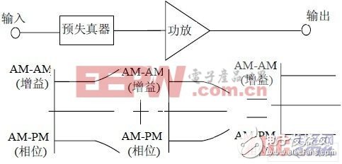
Figure 6 Predistortion block diagram
In order to ensure sufficient cancellation effect, the general pre-distortion adopts a double-loop structure, and its implementation block diagram is shown in FIG. 7.

Figure 7 Analog predistortion implementation block diagram
The paths III and IV constitute a predistortion generating loop, and after the combining, the necessary attenuation and phase shifting through the path V is combined with the main signal of the path I to finally complete the predistortion effect. The device selection of the IM3 generator on the general path IV is relatively strict. The whole circuit needs two channels of IV and V, and the attenuation and phase are strictly adjusted at the same time. The structure is complicated and the debugging difficulty is also high.
Oil Type Distribution Transformer
Henan New Electric Power Co.,Ltd. is a comprehensive enterprise integrating product research and development, product sales, and import and export services. It has more than 45 years of research and development experience. The company has a modern workshop of more than 120,000 square meters, a research and development center, and a staff apartment of more than 30,000 square meters. The production equipment is perfect, the testing method is perfect, the technical force is strong, and the qualification is complete. We can provide high, medium and low voltage transformers with voltages of 110KV and below and capacities of 120,000 kVA and below for various purposes, as well as tap changers, gas relays, oil level gauges, moisture absorbers, valves, thermometers, insulators, fans and other accessories .
The performances of model S9-M, S10-M, S11-M 10kv-35KV series full-sealed oil-immersed distribution transformes conform to Standards IEC IEEE. Its core is made of quality cold-rolled silicon sheet and is of a full-miter non-puncture structure and its coil is made of quality oxygen-free copper.
Main Functions And Features
It adopts radiator oil tank of corrugated shteet type or expansion type. As it doesn't need oil conservator, the height of
transformer is reduced, and as the transformer oil doesn't contract with air, the oil ageing is retarded, thus prolonging the
service life of transformer. The no-load loss of Model S10-M is 20% lower than that of Model S9-M, and S11-M is 30% lower thanS9-M.
Capacity: 30KVA-2500KVA
Primary voltage: 6KV-35KV
Secondary voltage: 220V-480V
Power frequency: 50Hz - 60Hz
Winding material: copper/aluminum
Altitude: no more than 1000m
Oil Type Distribution Transformer,Transformer 33Kv,Distribution Transformer,1000Kva Transformers,11KV oil Transformer
Henan New Electric Power Co.,Ltd. , https://www.newelectricpower.com
