![]()
|
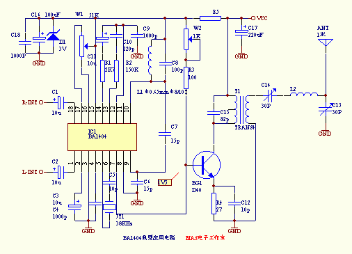
This article introduces you to a small stereo FM transmitter with BA1404 as the core. Because many friends are very enthusiastic about him and asked me about its information, I put it on. In fact, there are many introductions about the application of BA1404 in many electronic magazines and newspapers, which is not new, but he is indeed very practical. BA1404 is a special integrated circuit for FM radio transmission produced by American ROHM company; its high integration; few peripheral components required; reliable operation; wide range of power supply voltage, it can still work normally when it is as low as 1.5V, it is suitable for production under amateur conditions Various radio transmitters. Since I do n’t have a scanner, I can only draw a typical circuit in PROTEL. In WORD, I draw its internal functional block diagram and pin diagram to introduce to everyone. It is said that this circuit can reach 1000 with a higher sensitivity FM radio. M, you can go to trial production, as shown in Figure 1. The internal structure and pin diagram are shown in Figure 2. It is particularly pointed out that the 38KHz crystal oscillator is difficult to find. You can use a 57P Capacitor balance circuit between pins 5 and 6 to replace the work, but the three-dimensional effect is not too obvious! With him you can make your own small stereo radio station! It should be noted that the transistor used in the power amplifier stage in the original picture is 2SC8050. In fact, everyone knows that the highest frequency of 2SC8050 is about 100MHz. It is very inappropriate to use it here. It will burn out in a short time due to excessive fever and rapid fever. It's better to use domestically produced 3DG130C or 3DG12C and other domestic medium power tubes with a cooling cap effect. If you use Taiwan-made D40, D50 and other launching special tubes, the effect will be better, but the working point needs to be adjusted again. Note: Due to my negligence that the power amplifier stage is not connected to the power supply, the upper part of T1 should be connected to the + 4.5-6V power supply terminal. Based on the previous circuit diagram, an output filter circuit is added to make the circuit more complete and the frequency performance better.
In-depth analysis of the first-level cache and second-level cache of the technical zone CPU eMMC mass burning dilemma, do you really know? Isolation flyback and non-isolated BUCK application design plan Schottky barrier diode selection and application guide How to use Altium in program design Designer puzzle?  Follow WeChat Interesting and informative information and technical dry goods  Download Audiophile APP Create your own personal electronic circle  Follow the audiophile class Lock the latest course activities and technical live broadcast Collect People collection share it: ![]() '+ data.username +' '+ data.username +'
|


