
Practical circuit using STK3048 and STK6153 This article introduces a power amplifier thick film integrated circuit STK3048 and STK6153, the sound quality of the playback is impressive, the cost performance is extremely high, especially suitable for beginners and friends who prefer to set up a successful production. [Circuit principle]
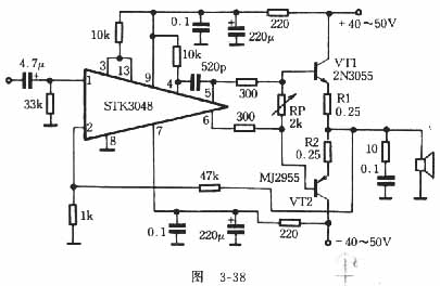
Figure 3-38 is a circuit diagram of using STK3048 to push the power tube 2N3055 and MJ2955. The circuit is so simple that there can be no more components. R1 and R2 can be used directly on the finished board. If the tube is not hot after being energized; if there is no other abnormality, you can adjust the RP without load, so that the voltage drop on R1 and R2 is 10 ~ 13mV, so that the quiescent current of VT1 and VT2 is 40 ~ 50mA, working in Class A and B. When soldering, the decoupling capacitor and pin (8) of the integrated circuit can be soldered together, and the other input “ground†terminals are connected here. If the midpoint voltage is greater than 10mV, it can be connected to the servo circuit (this article actually measured 30mV). After adjustment, the speaker can be connected to work. When I auditioned, I felt no worse than some mid-range aircraft.
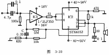
(2) Push STK6153 with LF353 No debugging is required for this circuit. During the audition, I felt that the treble sound was surprisingly bright, and even felt a little exaggerated, but it was very transparent, without any reluctance. The subjective evaluation is clearer than that of the LM3886 of TDA1514, the bounce and texture of the bass are also quite strong, and the listening feeling is very good. |

Follow WeChat

Download Audiophile APP

Follow the audiophile class
related suggestion
The inverter introduced here (see Figure 1) is mainly composed of MOS field effect transistors and common power transformers. Its output power depends on MO ...
The cell area we refer to here refers to the radius
Author: Lin Changhao This article describes several mining ...
![[Photo] Using MEC002A to make a remote FM transmitter](http://i.bosscdn.com/blog/20/06/41/5204128230.gif)
The Class A transistor power amplifier has a warm and sweet tone, which makes people tempted. But the temperature rise of Class A amplifier ...
![[Photo] Class A power amplifier using SAP15N / P audio pair tube ...](http://i.bosscdn.com/blog/20/06/41/513346769.gif)
The circuit is shown in Figure 5, ...
![[Photo] Using TDA7294 and 2SA1216 / 2S ...](http://i.bosscdn.com/blog/20/06/41/4233420295.gif)
'+ data.data.username +' '; dom + ='
Solar Street Light is 25Watt Solar Area Lighting with PIR Motion Sensor and Light Sensor Waterproof IP65 Led Street Light Dusk to Dawn for Outdoor. Solar Street lights are raised light sources which are powered by solar panels generally,LED is usually used as lighting source of modern solar street light, as the LED will provide much higher Lumens with lower energy consumption.This is one of the most convenient and versatile Solar Street Lamp on the market,it is waterproof IP65 aluminum alloy and toughened glass housing integrates the solar panel, the replaceable lithium ion batteries, and the dusk-to-dawn timing controller all into one unit.Led Solar Street's Installation is as simple as bolting the light onto a pole or flat surface by using its integrated bracke.there are no wires to connect whatsoever! The light is fully automatic. Solar Panel Street Light takes approximately 9-10 hours of direct sunlight to fully charge, with the panel facing south. Solar Street Light is Designed for modern homes, lighting up entrance, gardens, yards, pools and recreation areas.

Solar Street Light
Solar Street Lamp,Led Solar Street,Solar Panel Street Light,Solar Street Light
Shenzhen Bbier Lighting Co., Ltd , https://www.chinabbier.com