
1.2.2 Doppler signal demodulation method
The signal received by the transducer in CW Doppler flow measurement can be regarded as the superposition of multiple Doppler frequency shift components, expressed as:
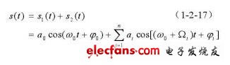
Where ai is the amplitude of the frequency shift component, Ωi is the frequency of the frequency shift component, φi is the initial phase of the frequency shift component, and s1 (t) is the signal that is coupled to the receiving probe via the non-moving medium such as the tube wall and lining.
The purpose of Doppler signal demodulation is to extract frequency shift information. Ideal demodulation should be proportional to
![]()
Output. At present, there are four commonly used demodulation methods: amplitude detection, frequency detection, phase detection, and multiplier detection. However, since s (t) is nonlinearly modulated by the Doppler shift component, there are two solutions: amplitude detection and phase detection. The modulation method will produce distortion, and the voltage amplitude of the frequency detection output will contain an amount proportional to the frequency shift Ωi, which is also undesirable. The reference signal cosω0t of the multiplier detection is multiplied by the received signal s (t), and then the high-frequency component is filtered by a low-pass filter to obtain the output:

The output obtained by this method does not cause distortion, so it is widely used in traditional industrial pipeline ultrasonic Doppler flowmeters.
1.2.3 Extraction of velocity information
Existing industrial pipeline ultrasonic Doppler flowmeters cannot determine the direction of flow velocity. In the field of medical blood flow measurement, the extraction of flow velocity direction information is mainly time domain method, frequency domain method and phase domain method, which are introduced as follows:
(1) Time domain method
The basic principle is to send the received ultrasonic Doppler signal s (t) to two multipliers at the same time, and multiply the two co-frequency signals cosωot and cos (ω0t + β0) with a certain phase difference β0, and then lower Pass filtering removes high frequency components, so the first output is:

The output of the second channel is:

If the direction of blood flow is positive, then Ωi》 0, the phase of the first output leads the phase of the second output; if the direction of blood flow is negative, then Ωi》 0, the phase of the second output leads the first output Phase. Therefore, the direction information of the bleeding flow can be detected by comparing the time sequence of the two outputs.
Auto transfer swtich-ATS panel
. ATS panel
. ATS Switcher: ABB, Socomec, Chint, SmartGen, Askai
. ATS for two Generators
. ATS for Generator and Mains
. 25A-6300A
Auto Start,Ats Panel,Auto Load Transfer,Auto Transfer System, ATS, AMF
Guangdong Superwatt Power Equipment Co., Ltd , https://www.swtgenset.com