Its scope of application is AC 50Hz rated voltage 380V, rated current to 250A.
The leakage protection device in the low-voltage distribution system is one of the effective measures to prevent personal electric shock accidents, and it is also a technical measure to prevent electric fire and electric equipment damage caused by electric leakage. However, the installation of leakage protectors does not mean that it is absolutely safe. Prevention should be the main method of operation, and other technical measures to prevent electric shock and damage to electrical equipment should also be taken at the same time.
Leakage protector structure:
Leakage protectors are mainly composed of three parts: detection components, intermediate amplification components, and operating actuators.
1 detection element. It consists of a zero-sequence transformer, detects the leakage current, and sends a signal.
2 enlarge the link. The weak leakage signal is amplified, and different devices (magnifying parts can be used as mechanical devices or electronic devices) constitute an electromagnetic protector-phase electronic protection device.
3 executing agency. After the signal is received, the main switch is switched from the closed position to the disconnected position, thereby cutting off the power supply and is a tripping part of the circuit to be protected from the grid.
Leakage protector works:
Leakage protectors mainly include several components such as detection components (zero-sequence current transformers), intermediate links (including amplifiers, comparators, trip units, etc.), actuators (main switch), and test components.
The schematic diagram of the working principle of the leakage protector of the three-phase four-wire power supply system. TA is a zero-sequence current transformer, GF is the main switch, and TL is the shunt trip coil of the main switch.
When the circuit to be protected is working properly and there is no leakage or electric shock, according to the Kirchhoff's law, the current phasor passing through the primary side of TA is equal to zero, ie, the secondary side of TA does not generate induced electromotive force and leakage protection. The device does not move and the system maintains normal power supply.
When a leakage occurs in the protected circuit or an electric shock occurs, the leakage current Ik is generated because the phasor of each phase current on the primary side of the TA is no longer equal to zero.
In the core there is an alternating magnetic flux. Under the action of the alternating magnetic flux, the secondary coil of the TL generates the induced electromotive force. This leakage signal is processed and compared by the intermediate link. When the predetermined value is reached, the main switch's shunt release coil TL is energized, driving the master. The switch GF automatically trips and cuts off the faulty circuit to achieve protection.
The working principle of the leakage protector for single-phase circuit and three-phase three-wire system is the same.
The range of installed leakage protectors:
The National Standard GB13955-1992 "Installation and Operation of Leakage Current Protectors" promulgated by the State Bureau of Technical Supervision in 1992 made uniform provisions for the installation of earth leakage protectors in urban and rural areas throughout the country.
2.1 Equipment and location where leakage protectors (leakage switches) must be installed (1) Portable electrical equipment and hand-held power tools belonging to Class I (Class I electrical products, meaning that the product's protection against electric shock depends not only on the basic insulation of the equipment, but also Also includes an additional safety precaution, such as product housing grounding;
(2) Electrical equipment installed in humid and corrosive places;
(3) Electrical construction machinery and equipment at the construction site;
(4) Provisional electrical equipment for temporary use;
(5) In-room outlet circuit of hotels, restaurants and hostels;
(6) Outlet loops in buildings, schools, companies, and residential buildings;
(7) Water lighting equipment for swimming pools, fountains, and baths;
(8) Power supply lines and equipment installed in the water;
(9) Electrical medical devices that are in direct contact with the human body in hospitals;
(10) Other places where an earth leakage protector needs to be installed.
2.2 Application of Alarm Type Leakage Protector For electrical devices or places that may cause accidents or major economic losses in the event of a leakage current interruption, an alarm type leakage protection device should be installed, such as:
(1) Access lighting and emergency lighting in public places;
(2) Fire-fighting elevators and equipment for ensuring the safety of public places;
(3) Power supply for fire-fighting equipment, such as fire alarm devices, fire-fighting pumps, fire-fighting tunnel lighting, etc.;
(4) Power supply for anti-theft alarms;
(5) Other special equipment and places that do not allow power outages.
The main technical parameters of the leakage protection device The main operating performance parameters are: rated leakage action current, rated leakage action time, rated leakage action current. Other parameters include: power frequency, rated voltage, rated current, etc.
1 Rated leakage current The current value at which the leakage protector operates under the specified conditions. For example, a 30mA protector, when the input current reaches 30mA, the protector will act to disconnect the power.
2 Rated leakage current The current value of the leakage protection device does not operate under the specified conditions, generally one half of the leakage operation current value should be selected. For example, a leakage protector with a leakage action current of 30 mA, the protector should not operate when the current value is less than 15 mA. Otherwise, the sensitivity is too high and it is easy to malfunction, affecting the normal operation of the electrical equipment.
3 The rated leakage operation time is the time from the sudden application of the rated leakage operation current until the protection circuit is cut off. For example, a 30mA×0.1s protector, from the current value up to 30mA, to the main contact separation time does not exceed 0.1s.
4 other parameters such as: power frequency, rated voltage, rated current, etc., in the selection of leakage protection device, should be used with the line and electrical equipment to adapt. The operating voltage of the earth leakage protector must adapt to the rated voltage of the normal fluctuation range of the electric network. If the fluctuation is too large, it will affect the normal operation of the protector. Especially for electronic products, the action will be rejected if the supply voltage is lower than the rated operating voltage of the protector. The rated operating current of the leakage protector must also be the same as the actual current in the circuit. If the actual operating current is greater than the rated current of the protector, overload is caused and the protector malfunctions.
Micro motors Based on Dc Motor, micro motor belongs to the small size of dc motor,micro motor rotor, back cover, chassis, rotor winding is mainly copper, back cover most of the use of plastic material, motor shell use galvanized steel plate, the micro motor can be ROHS test.
A micro motor is any of a class of rotary electrical machines that converts direct current electrical energy into mechanical energy. The most common types rely on the forces produced by magnetic fields. Nearly all types of micro motors have some internal mechanism, either electromechanical or electronic, to periodically change the direction of current flow in part of the motor.
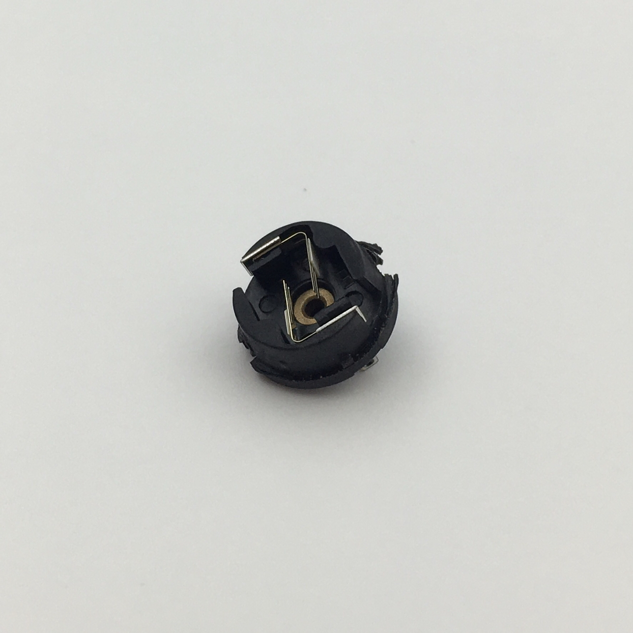
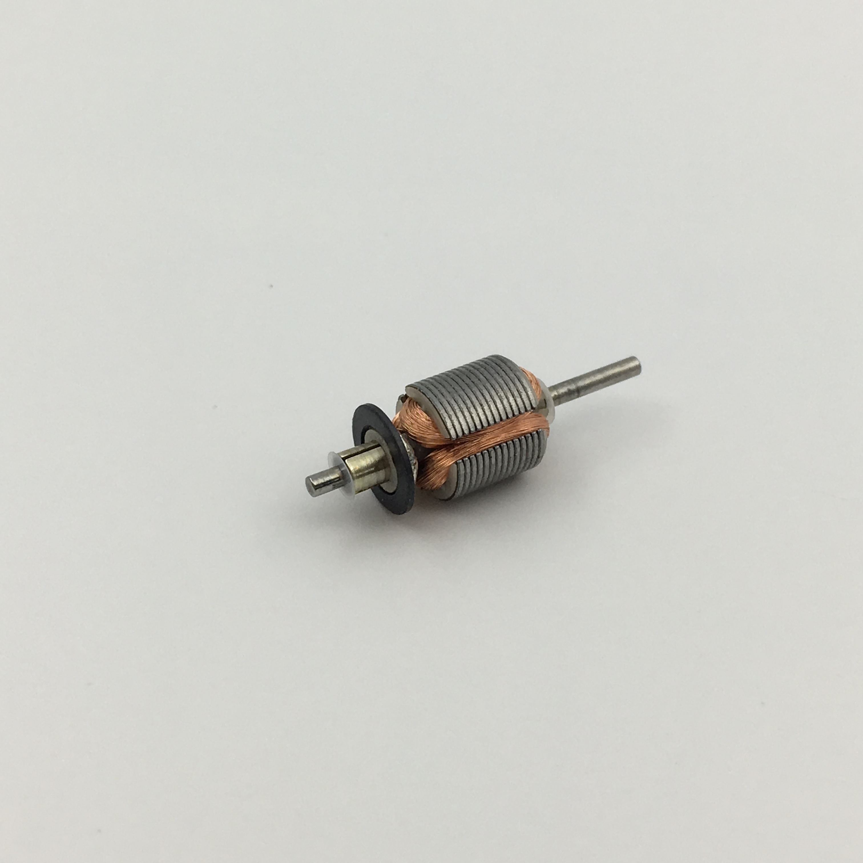
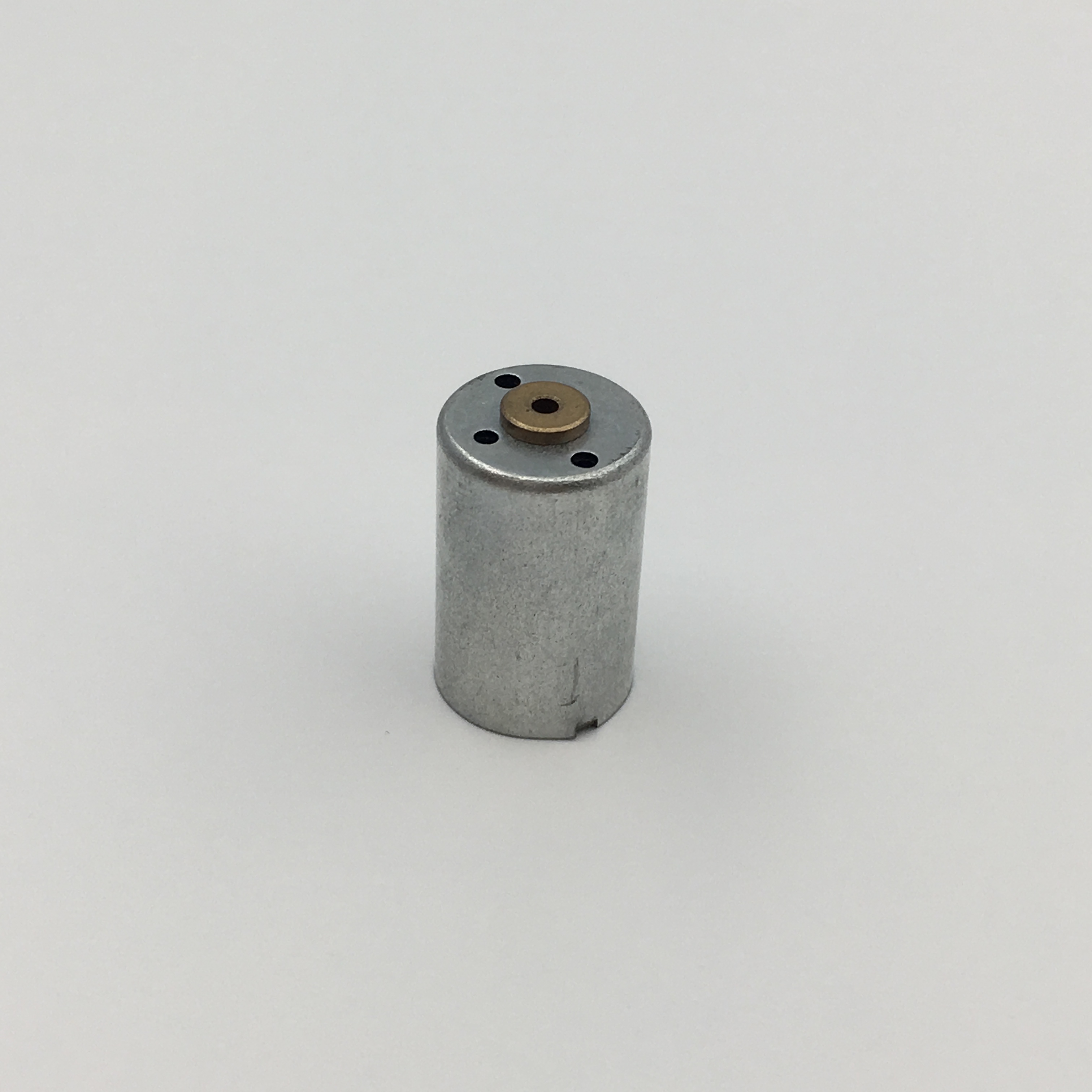
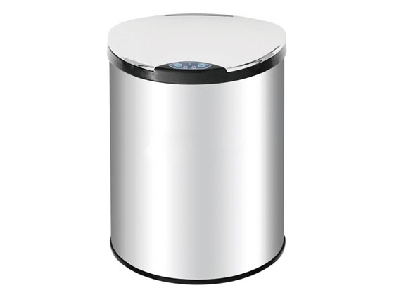
Micro motor is mainly used in: outdoor lamps, electronic toys, model aircraft, intelligent bin, breeze machine, etc


Method of use: the best stable in horizontal plane, installed on the Micro motor output shaft parts, cannot use a hammer to knock, knock prone to press into the micro motor drive, may cause damage to internal components, and cannot be used in the case of blocked.
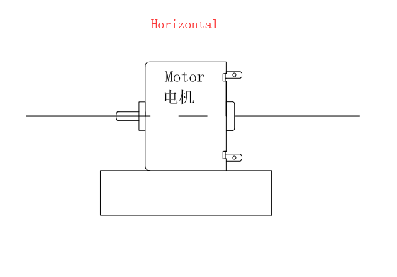
Operating temperature range:
Micro motor should be used at a temperature of -10~60℃.
The figures stated in the catalog specifications are based on use at ordinary room temperature catalog specifications re based on use at ordinary room temperature (approximately20~25℃.
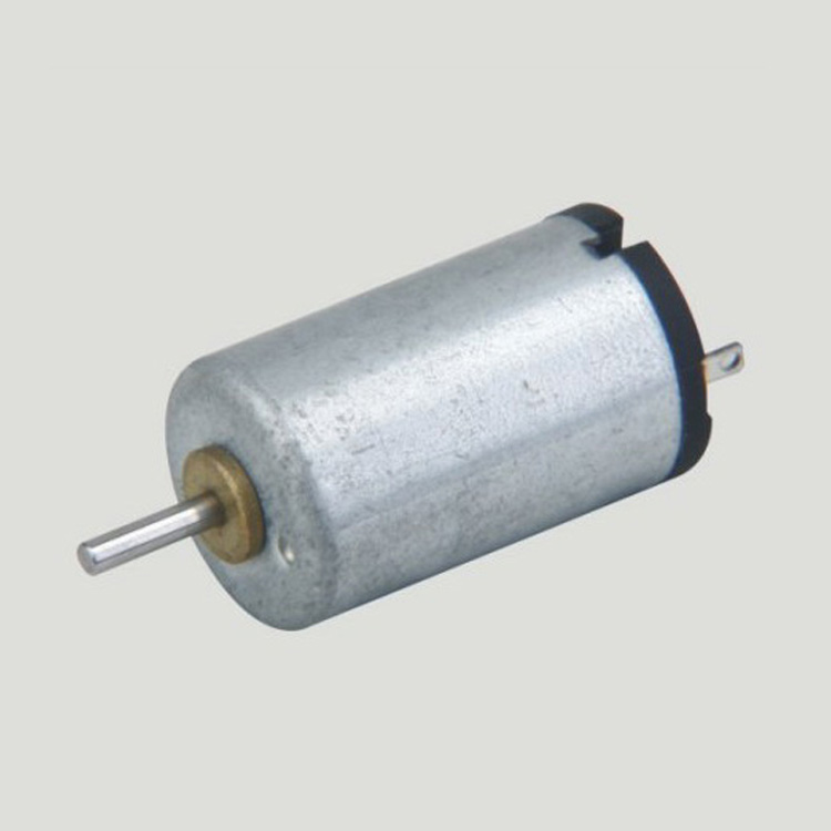
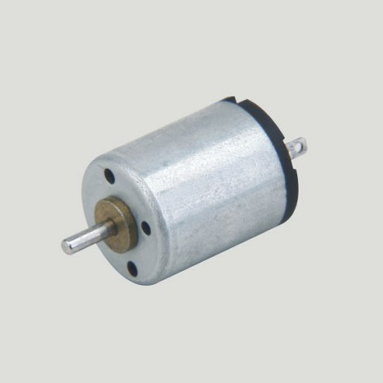
If a micro motor is used outside the prescribed temperature range,the grease on the gearhead area will become unable to function normally and the motor will become unable to start.Depending on the temperature conditions ,it may be possible to deal with them by changing the grease of the motor's parts.Please feel free to consult with us about this.
Storage temperature range:
Micro motor should be stored ta a temperature of -15~65℃.
In case of storage outside this range,the grease on the gearhead area will become unable to function normally and the motor will become unable to start.
Service life:
The longevity of micro motor is greatly affected by the load conditions , the mode of operation,the environment of use ,etc.Therefore,it is necessary to check the conditions under which the product will actually be used .The following conditions will have a negative effect on longevity.Please consult with us should any of them apply.
â—Use with a load that exceeds the rated torque
â—Frequent starting
â—Momentary reversals of turning direction
â—Impact loads
â—Long-term continuous operation
â—Forced turning using the output shaft
â—Use in which the permitted overhang load or the permitted thrust load is exceeded
â—A pulse drive ,e.g.,a short break,counter electromotive force,PWM control
â—Use of a voltage that is nonstandard as regards the rated voltage
â—Use outside the prescribed temperature or relative-humidity range,or in a special environment.
â—Please consult with us about these or any other conditions of use that may apply,so that we can be sure that you select the most appropriate model.
when it come to volume production,we're a major player as well .each month,we rurn out 600000 units,all of which are compliant with the rohs directive.Have any questions or special needed, please contact us, we have the engineer group and best sales department to service to you Looking forward to your inquiry. Welcome to our factory.

Micro Motor,Micro Dc Motor,Micro Vibration Motor,Micro Electrical Motor
Shenzhen Shunchang Motor Co., LTD. , https://www.scgearmotor.com
