
Abstract AT89S52 microcontroller to control the core of the intelligent vehicle systems simple design. The system controls the trolley to perform corresponding motion on the seesaw according to the signal detected by the angle sensor, wherein the angle sensor is used to sense whether the horizontal angle of the panel is zero, and the trolley is balanced. At the same time, the reflective photoelectric sensor is used to sense the board guide line to ensure that the car does not leave the track and guide the car to climb the board surface in the specified area. The system display device adopts RT1602 liquid crystal display, which can display line spacing and time in real time. The power source of the trolley adopts stepping motor and is driven by the bridge circuit formed by SFA475 integrated transistor chip. The power supply is directly powered by 12 V battery, and the MCU detects according to each module. The signal makes a judgment to ensure that the car is operating normally.
This article refers to the address: http://
Intelligent vehicle is a comprehensive system integrating environment sensing, planning decision-making, automatic driving and other functions. It is a typical high-tech complex with centralized application of computer, sensing, information, communication, navigation, artificial intelligence and automatic control. The intelligent and simple vehicle system designed in this paper is an attempt of this complex. The system enables the intelligent simple vehicle to realize the functions of automatic tracing and balance detection under the cooperation of various sensors, and has basically realized the intelligence of the vehicle.
1 Intelligent simple vehicle circuit overall structure design
The simple intelligent vehicle system in this paper is realized through the experiment of electric vehicle raft. The AT89S52 is used as the control core of the electric vehicle raft. The infrared sensor is used to detect whether the trolley is moving in the orbit. If the trolley deviates from the orbit, the sensor will send a signal to the single-chip microcomputer to control the rotation of the stepper motor. At the same time, the angle sensor is used to identify whether the trolley has reached the equilibrium position.
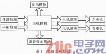
The overall circuit system includes six parts: a host control module, a balance detection module, a tracking detection module, a display module, an electric drive module, and a voice prompt module. The host control module is the core of the circuit system, and the signals detected by the balance detection module and the tracing module are processed and output to the motor drive module to control the left and right motors, thereby controlling the forward and backward movement of the trolley. At the same time, the main control module also outputs a control signal to the display module to display the line spacing and time, and controls the voice prompt module to send a prompt tone. The circuit system block diagram is shown in Figure 1.
2 electrical hardware design
2.1 Host Control Module
The host control module uses ATMEL's low-voltage, high-performance 8-bit single-chip AT89S52, which contains 8 kB of repetitive read-only memory and 256 Byte of random data memory, characterized by high density, non-volatile Storage, micro power consumption, system stability and high reliability. In addition, the AT89S52 technology is mature, the price is low, the reference resources are abundant, and the application is also extensive. In addition, the system can make the MCU resources fully used, so it is selected as the core control of the smart car circuit.
2.2 display module
The display module uses a 16-character liquid crystal (LED) display. The liquid crystal display has the advantages of low power consumption, flat right angle display, large visible area, good picture effect, high resolution and strong anti-interference ability. It can directly use the I/O port on the MCU, and can realize multiple functions without too many peripheral devices.
2.3 Motor and drive module
The motor part of the motor and the drive module adopts a stepping motor, which has large torque and high precision and only receives one pulse. It can be rotated by a fixed angle. Therefore, the use of a bridge-type drive circuit composed of transistors can better control the speed, path, and steering of the stepping motor, and can achieve precise control and the system is relatively stable. In addition, because the system has high requirements on the accuracy and sensitivity of the motor, and the combination of the stepping motor and the driving circuit can fully meet this requirement, a stepping motor and a driving circuit are adopted.
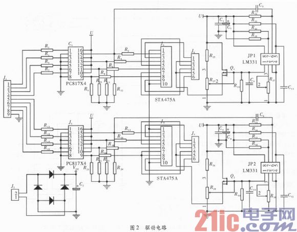
The drive circuit is shown in Figure 2. The driving module is the power source of the design. For this reason, before the signal line is connected with the main control board interface, the optocoupler device PC817 is used for isolation to prevent the large current in the circuit from burning the main control board device; considering the output torque of the stepping motor The operating frequency drops faster, and the voltage required at low frequencies is too low. If a higher voltage is used, it is possible to burn the driving of the stepping motor. To achieve accurate control of the trolley, there is a certain requirement for the driving, which requires basic Meet the balance torque output. STA475A is a motor driver chip widely used in printers and various drive control boards, and its NPN type Darlington tube. Here, a frequency voltage conversion circuit is employed to compensate the voltage required for the high frequency operation of the stepping motor. The function of the V/F conversion device LM331 is to convert the frequency signal into a voltage signal, and use this signal to control the high-power current limiting FET to ensure that the driving current is not reduced due to the excessive frequency, and the constant torque is output, thereby ensuring The torque of the motor can drive the electric vehicle to run smoothly.
2.4 tracing module
The automatic tracing is based on the Auto-Guided Vehicle (AGV) system, which realizes the automatic identification of the car, determines and automatically avoids obstacles, and selects the correct route. It uses a line that is significantly different from the ground color as a guide, and uses the sensor to sense the guide line and the obstacle to judge.
There are many ways to realize the visual and proximity function of the robot: (1) The CCD camera can be used for image acquisition and recognition methods, but it is not suitable for small-volume systems, and also involves image acquisition, image recognition and other fields. (2) Capacitive proximity sensor based on the change in capacitance when the surface of the object is close to the sensing element. (3) An ultrasonic sensor detects the proximity of an object based on the influence of the wave during its propagation from transmission to reception. (4) An infrared reflective photoelectric sensor comprising a solid state light emitting diode that emits infrared light and a solid state light emitting diode that functions as a receiver.
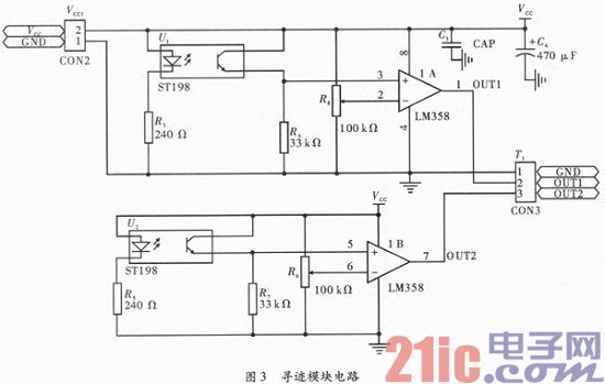
The tracking detection module of the system uses a reflective infrared sensor to detect the black line on the raft. Since the black line can be drawn directly on the slab track with a black pen, the influence of the quality on the slab can be ignored. The infrared sensor emits and receives invisible light, has strong anti-interference ability, high sensitivity, small size, light weight, simple peripheral circuit and convenient installation. Therefore, it is ideal for short-distance detection. The circuit of the tracing module is shown in Figure 3. The voltage of the integrated reflective photoelectric sensor ST198 is 4.5 to 5 V. When the emitting diode is turned on, infrared light is emitted, so that the resistance between the collector and the emitter of the receiving tube becomes small, and the potential of the comparator positive input terminal is pulled high. When the infrared light is irradiated onto the black line, the reflected light is compared. When the resistance between the collector and the emitter of the receiving tube increases, the potential of the comparator forward input terminal is pulled low, and the MCU controls the forward and reverse rotation of the motor according to the signal.
2.5 Balance Detection Module
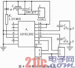
The balance detection module circuit is shown in Figure 4. Using the ADXL202, a dual-axis accelerometer from Analog Devices, the product is low in cost, low in power consumption, and integrated with internal sensitive components and subsequent circuits. The ADXL202 sensor has a simple peripheral circuit and a digital signal at the same time. It has strong anti-interference, high sensitivity and easy control by single-chip microcomputer. Therefore, this sensor is selected as the balance detection module of this system.
3 software design
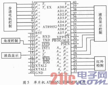
According to the selection of each system module, make full use of the resources of the single-chip AT89S52, and allocate the following resources to the single-chip system resources: P1 port control stepper motor, P0 port and P2.5, P2.6, P2.7 control liquid crystal display, P2.1 ~ P2.4 is connected to the infrared detection module, P3.2 connection angle detection mode is fast, P2.0, P3.7 is connected to the transfer switch, as shown in Figure 5.
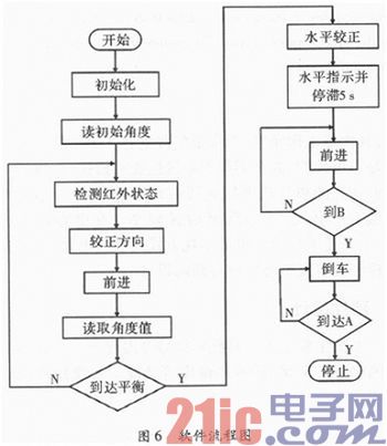
When the system starts running, the MCU first reads the initial angle of the motor, then reads the signal detected by the current infrared sensor from P2.1~P2.4, determines whether the car is in the track, and then corrects the direction of the car. The MCU is from P1. The .0 to P1.7 mouth pulse controls the rotation of the motor to advance the car. In the trolley movement, the angle sensor sends the detected signal to the single-chip microcomputer, and the single-chip microcomputer determines whether the trolley reaches the equilibrium position. When the balance position is reached, the angle sensor level is correct, and the car continues to advance after 5 s. When the end of the track is reached, the vehicle returns to the origin, and the software flow is shown in Figure 6.
4 Conclusion
After many tests, the system is not easy to control except the mechanical part, the circuit and the running part are relatively stable, and the simple vehicle can automatically complete the forward and backward movements on the seesaw. The design also adds protection to the entire system, such as the use of V / F technology to assist the motor control, to ensure that the motor can provide enough torque for the car load. In addition, voice prompts, humanized display and other functions have been added to the system to make the system more intelligent and user-friendly. At the same time, each circuit module also has overcurrent protection, debounce and other auxiliary circuits to make the whole system more secure and stable.
Medical Pressure Gauge,Mini-Sized Gauge Medical Device,Oxygen Cylinder Gauge,Oxygen Tank Gauge
ZHOUSHAN JIAERLING METER CO.,LTD , https://www.zsjrlmeter.com