
In order to allow users in the cockpit to obtain accurate and reliable information at any time, the display used in the cockpit must have high reliability, and at the same time, because the pilot of the plane must operate the instrument both right and left, and in order to improve the legibility of the cockpit display and relieve visual fatigue. The light intensity of the monitor should also be automatically and manually adjusted according to the surrounding environment and the needs of the user, so as to prevent the user from seeing the display content when the ambient light is strong or feeling dazzling when the ambient light is very dark. The brightness of the backlight of the LCD directly determines the average brightness of the display, and the brightness of the display is adjusted by adjusting the brightness of the backlight of the LCD.
The author adopts domestic STC12C5624AD one-chip computer to design a liquid crystal screen backlight module to drive and adjust the circuit, can measure the illumination intensity of the ambient light accurately, realize the automatic and manual adjustment of the luminance of the back light according to the ambient light.
1 Display backlight adjustment principle
Because of the particularity of the aircraft cockpit, there is a higher requirement for the reliability, accuracy, and intelligence of the cockpit display. The backlight brightness of the cockpit display needs to be automatically adjusted according to changes in the ambient light so that the human eye can see more comfortable, and the screen can be manually adjusted. Brightness to meet the user's requirements. The relationship between the ambient light xt and the brightness yt of the backlit screen can be obtained through research.
When the ambient light is xt, the automatically adjusted brightness is:
Yt=kxt+b (1)
Where b is the minimum brightness required for the driver to see the information displayed on the screen when the ambient light is 0; k is a proportional constant that can be modified according to the user's habits, reflecting the human seeing the screen in a bright environment The information required is the ratio of brightness to ambient light.
When the user is not satisfied with the automatically adjusted brightness, manually adjusting the brightness to yt' invokes the following formula:
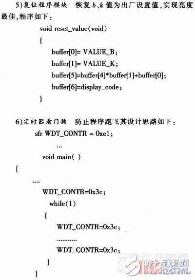
The resulting b' and k' are checked and replaced with b and k in equation (1) to obtain a new calculation formula. In order to prevent excessive adjustment by the driver, bmin and bmax are set, only b' is between the two. When b' is used instead of b, the initial value bs is set by the system at the time of shipment. The user can restore b to bs by pressing the button, and also set kmin, kmax, and ks for k.
2 Circuit
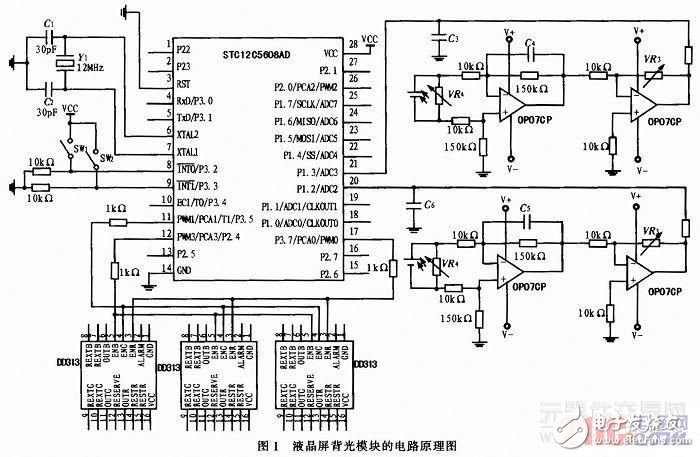
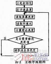
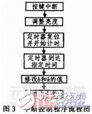
LCD circuit backlight module schematic diagram shown in Figure 1, mainly including two PN23CV-type silicon photovoltaic cells, single-chip, button circuits, to DD313 as the core of the LED backlight driver circuit and auxiliary circuits. The PN23CV silicon photocell senses the ambient light illumination and the brightness of the backlight of the LCD screen. After amplification, the signal is sent to the SCM. The SCM calculates the theoretical brightness of the LCD backlight and compares it with the actual brightness of the LCD backlight to determine whether the LCD needs to be adjusted. The brightness of the screen backlight. If necessary, give the DD313 as the core of the backlight drive circuit to send signals, which DD313 13,11,6 pins respectively connected to red, green, blue LED, control the brightness of the LED, and then adjust the actual brightness of the LCD backlight module. When the user is not satisfied with the result of the automatic adjustment, the signal can be sent to the SCM through the button circuit, and the SCM determines whether it is necessary to adjust the brightness of the backlight of the LCD screen. After adjusting the brightness of the backlight of the LCD screen, delay the time and modify the b and k values. Circuit program flow chart shown in Figure 2 and Figure 3.
When the user manually adjusts the display brightness, the buttons SW1 and SW2 are connected to interrupt 0 and interrupt 1 of the microcontroller STC12C5624AD respectively. Press the button to output the voltage as VCC, release the button, the output voltage is 0, press SW1 to indicate that the user requests to increase the display brightness, press SW2 to indicate that the user requests to decrease the display brightness, SW1 and SW2 are pressed to return to the original factory b and The setting values ​​of k and bs and ks, SW1 and SW2 are respectively connected to pins 8 and 9 of the single-chip microcomputer.
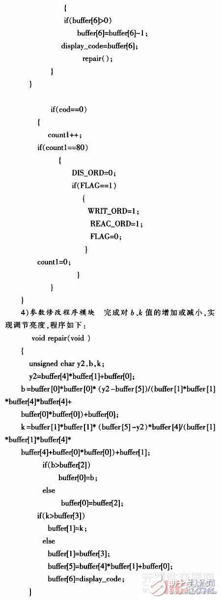
3 Software Programming
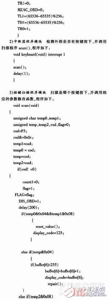
The circuit function is realized by software programming. Use the STC single-chip timer and interrupter to scan whether there is a key press and do the corresponding processing.
4 Conclusion
The 51-bit microcomputer with superior performance and mature technology is used to manually and automatically adjust the backlight of the cockpit display through the design of the peripheral circuit of the microcontroller and the programming of its timers and interrupts, so as to achieve a comfortable screen brightness that satisfies the user and enables the cockpit display. The backlight adjustment is precise and reliable while being more intelligent and user-friendly.
Middle-low Level Commercial Sky Curtain
Middle-Low Level Commercial Sky Curtain,Outdoor Football Stadium Led Grille Screen,Transparent Led Grille Screen,Led Display Billboard
Kindwin Technology (H.K.) Limited , https://www.ktl-led.com