Currently, for many popular mobile phones (especially clamshell phones), the color LCD, OLED display or camera module CMOS sensor of the mobile phone is connected to the baseband controller through a flexible circuit or a long trace PCB. The cable is subject to interference from parasitic GSM/CDMA frequencies radiated by the antenna. At the same time, due to the introduction of high-resolution CMOS sensors and TFT modules, digital signals operate at higher frequencies, which can cause EMI interference or may cause ESD hazards like antennas.
Both such EMI and ESD interference can destroy the integrity of the video signal and even damage the baseband controller circuit. Driven by the trend of compact design, discrete filters do not provide any space savings for the solution, given the board constraints, high filtering performance on the operating frequency of the handset, and design constraints such as signal integrity, and can only provide for narrowband attenuation. Limited filtering performance, so most designers today use integrated EMI filters.
This article refers to the address: http://
With the increase in the resolution of LCD displays in portable devices such as mobile phones and cameras, the transmission rate of video signals is also increasing, and conventional filter solutions have gradually reached their technical limits. In phones with high-resolution displays and embedded cameras, the signal is transmitted from the baseband ASIC to the LCD and the embedded camera at a specific frequency (depending on the resolution). The higher the video resolution, the higher the frequency of data work. For example, for a camera module of 30 to 600 megapixels, the clock frequency is approximately between 6 and 12 MHz. It is therefore recommended to select the filter (upper and lower) cutoff frequencies in the range of 30 to 50 MHz. As resolution increases to millions of pixels, the clock frequency has exceeded 60 MHz, which requires a filter cutoff frequency of up to 300 MHz.
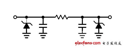
Figure 1: New filter cell structure (series resistance is 100 ohms, line capacitance is 20pF)
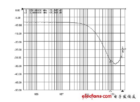
Figure 2: New RC filter S21 parameter curve.
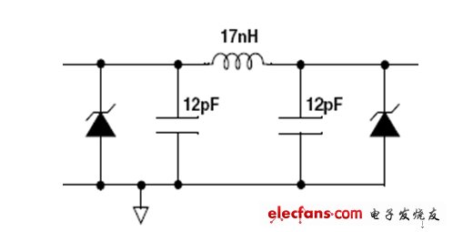
Figure 3: Inline electronic LC filter unit structure.
Faced with these trends in the mobile phone industry, traditional RC filter solutions are reaching their limits. In order to meet the ever-increasing video signal of mobile phones and the stronger anti-ESD surge capability, Yinglian Electronics has developed a new generation of EMI filters based on LC structure. This integrated LC filter structure can be used to provide a cutoff frequency of up to 350MHz and support data rates with clock frequencies in excess of 60MHz. It also provides excellent filtering performance with attenuation characteristics better than -25dB over the 800MHz to 2.5GHz frequency range. Figure 4 shows the S21 parameter specification using the basic unit architecture of this filter. In addition to the filtering function, the integrated input TVS tube also suppresses air discharge ESD strikes up to 15kV, meeting the performance levels required by the IEC61000-4-2 Level 4 industry standard.
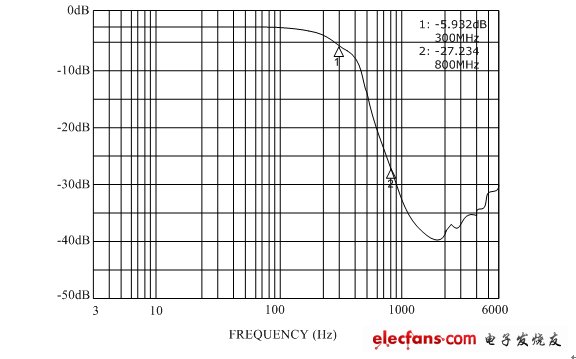
Figure 4: S21 parameter curve of the British Union electronic LC filter.
British Union's low-capacitance EMI filters UM4411, UM6411, and UM8411 support 4, 6 and 8-wire configurations, each of which includes a PI-type RC filter network with TVS tubes attached to it. The device is housed in a QFN package with 0.4mm pin pitch, which provides designers with ultra-thin mobile phones with ample design space. Especially on PCB layouts, some of the display I/O connectors have pin spacings of 0.4 mm. EMI filters in 0.4 mm pitch DFN packages will help system engineers lay out boards. In the choice of the device, it should be reasonably selected according to the number of data channels. Figure 5 shows some advantages of using an 8-channel filter and two 4-channel filters on the layout board. At the same time, an 8-channel filter is selected. It is also less expensive than two 4-channel filters.
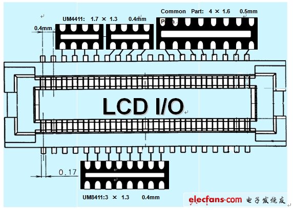
Figure 5 EMI filter pin spacing on the layout.
Fiber optic adapter are used in fiber optic connection, the typical use is to provide a cable to cable fiber connection. People sometimes also name them to be mating sleeves and hybrid adaptors, mating sleeves means this fiber optic adapter is used to connect the same type fiber optic connectors, while hybrid adaptors are the fiber optic adaptor types used to connect different kinds of fiber optic connectors. YLTelecom`s fiber adapter provide reliable solution for fiber connections, single mode fiber optic adaptors and multimode fiber optic adaptors available on request. We adopt high quality raw materials and make these fiber optic adapters strictly according to international standard, this makes our fiber optic adaptors with high performance.
Fiber Optic Adapters FC, SC, ST, LC, MT-RJ, MU, E2000, FC/APC, SC/APC, LC/APC, E2000/APC, Simplex, Duplex, Quad, mating sleeves, hybrid fiber optic adapters, Single mode fiber optic adapters, multimode fiber optic adapters are all available.
Fiber optic adapters (also called couplers) are designed to connect two fiber optic cables together. They come in versions to connect single fibers together (simplex), two fibers together (duplex), or sometimes four fibers together (quad).
Adapters are designed for multimode or singlemode cables. The singlemode adapters offer more precise alignment of the tips of the connectors (ferrules). It is ok to use singlemode adapters to connect multimode cables, but you should not use multimode adapters to connect singlemode cables. This can cause misalignment of the small singlemode fibers and loss of signal strength (attenuation).
When connecting two multimode fibers, you should always make sure they are the same core diameter (50/125 or 62.5/125). A mismatch here will cause attenuation in one direction (where the larger fiber is transmitting light into the smaller fiber).

Fiber optic adapters are typically connecting cables with similiar connectors (SC to SC, LC to LC, etc.). Some adapters, called "hybrid", accept different types of connectors (ST to SC, LC to SC, etc.). When the connectors have differing ferrule sizes (1.25mm to 2.5mm), as found in LC to SC adapters, the adapters are significantly more expensive because of a more complicated design/manufacturing process.
Fiber Optic Adapter, Fiber Optic Cable Adapter, SC Fiber Optic Adapter, ST Fiber Optic Adapter, FC Fiber Optic Adapter
NINGBO YULIANG TELECOM MUNICATIONS EQUIPMENT CO.,LTD. , https://www.yltelecom.com
