
Overview:
This article summarizes some common methods of secondary constant current in LED lighting power supply, hoping to help newcomers improve. It is no exaggeration to say that the LED driver power supply will directly determine the reliability and life of the LED lamp. As a power supply engineer, we know that the characteristics of LEDs require constant current drive to ensure uniform brightness and long-term reliable illumination.
First, let's talk about several constant current methods of the popular TL431.
Single TL431 constant current circuit 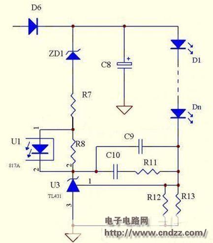
As shown above, it is a schematic diagram using a single TL431 constant current. The principle of this circuit is very simple, mainly using the 431's 2.495V reference for constant current, and also limits the voltage drop across the LED, but the advantages and disadvantages are equally obvious.
advantage:
The circuit is simple, the components are few, and the cost is low. Because the reference voltage precision of the TL431 is high, the R12 and T13 are only high-precision resistors, and the constant current precision is relatively high.
Disadvantages:
Since the TL431 is a 2.5V reference, the loss of the constant current sampling circuit is extremely large, and it is not suitable for a power supply with an excessive output current. The fatal flaw of this circuit is that it can not be idling, so it is not suitable for external LED power supply, so we have improved some defects of the line below.
Single TL431 constant current improved circuit 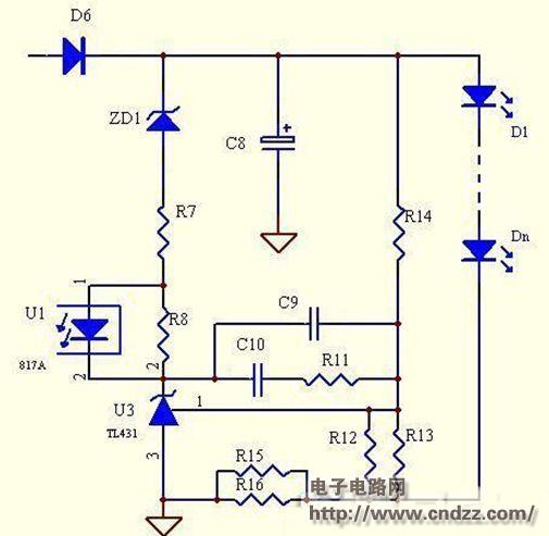
As shown in the above figure, it is an improved schematic diagram using a single TL431 constant current: this circuit also uses the TL431's 2.495V reference for constant current. The difference from the above circuit is that the voltage of the current sampling circuit is reduced, as long as the total Design the values ​​of R12, R13, R14 to limit the voltage drop across the LED.
advantage:
The circuit is simple, the components are few, and the cost is low. Compared with the above circuit, the power consumption of the sampling resistor is significantly reduced, the constant current precision is high, and the fatal defect that the above circuit cannot be idling is overcome, when there is individual LED breakdown. , can automatically adjust the output voltage.
Disadvantages:
When the output is unloaded, the output voltage will rise, and the rising range is determined by the ratio of the current sampling circuit resistance to R12 and R13. In fact, the real disadvantage of this circuit is that when the voltage drop consistency of a single LED is not high, the constant current point will change accordingly.
For example, the most common 12-string LED lights, the minimum voltage drop is about 35.5V, the highest return to about 37.4V (personal experience, of course, different manufacturers will be different), then the constant current accuracy will be 5% difference - 8%.
(Please read the PDF for details)
Multifunctional Power Meter,Power Meter,Multi-Function Ammeter,Multifunction Meter
zhejiangjinyidianqiyouxiangongsi , https://www.jooeei.com