
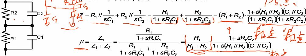
Today we came to learn about the stability criteria of operational amplifiers. We have previously explained the Bode plot. To add that, the twentieth episode analyses the poles and zeros of series and parallel of resistors and capacitors without analyzing the inductance. This is because the inductor is rarely used in general op amp circuits. Therefore, the circuit containing the inductor is not analyzed here. The reader can deduct it on its own. Continuing the previous section, as shown in the following figure, the resistor and the capacitor are connected in parallel and in series. Similarly, the impedance is first analyzed. For DC, it is equivalent to two resistors connected in series. For AC, it has a zero point. With two poles, and from the perspective of feedback, there is only one pole and zero, which is one pole less than the impedance. This is because the feedback is derived from the midpoint of the R1 and R2 connections.
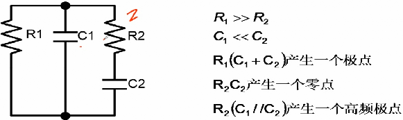
Let's look at the circuit below. Although it looks a bit messy, it actually has more applications. R1, R2, C1, C2, where C1 is usually a ceramic capacitor, the capacity is relatively small, and the pF level is adopted. C2 is an electrolytic capacitor that passes the uF level, but the electrolytic capacitor usually has a relatively large internal resistance, so the resistance of R2 is relatively small, and it is usually several ohms as the internal resistance of the electrolytic capacitor. R1 is the load, so the resistance of R1 is much larger than that of R2. Here two poles have a zero point, R1 (C1+C2) is the low frequency pole, R2C2 is the zero point, and R2 (C1//C2) is the high frequency pole, so the Bode diagram is that the DC gain is unchanged and then goes through the low frequency pole. Decrease by -20dB per decade, then pass the zero point, keep the gain constant, and finally go through the high frequency pole, the gain continues to decrease by -20dB per decade.
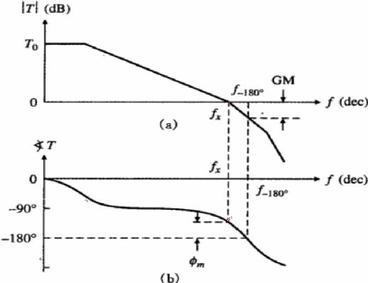
In this way, we look at the stability criterion. We also mentioned before, the phase margin and the gain margin. The following figure shows more clearly. For the open loop, the phase margin is 0 dB when the corresponding phase The angle plus 180, which is φm in the figure, generally speaking, the phase margin between 45 degrees and 60 degrees is appropriate, if the phase margin is relatively small, it is easy to be unstable, and the phase margin is equal to 0 degrees. Oscillation occurs. As the phase margin increases, the system responds to the input with overshoot. If the phase margin is large, the system does not overshoot exponentially to the specified value. The system response is slow, and the gain margin is The gain when the phase angle is -180 degrees is generally less than 0 dB, which is the GM in the figure.
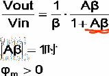
The stability criterion, when the loop gain is 1, the phase margin is greater than 0. The stability of the loop gain depends on the stability of the designed op amp circuit. When the loop gain is 1, it is also the transport. When the open-loop gain is set to 1/B, for example, for the non-inverting amplifier, the system gain is (1+(R2/R1)) times. Therefore, it is necessary to look at the open loop gain of the op amp (1+(R2/R1). )) corresponds to the phase angle. When the op amp is connected to a follower, its gain is 0 dB, which is relative to other amplification factors, and the corresponding phase margin is also the smallest, but its -3dB frequency is relatively large, so increase -3dB At the same time as the frequency, the phase angle margin becomes smaller, so it is still confirmed that sentence, for the mode of electricity, there is no best, only the most suitable. Similarly, when the open-loop op amp phase margin and gain margin satisfies the requirement, that is, the phase at 0 dB is greater than -180 degrees. Certainly, when the op amp circuit with other amplification is built in the closed loop, it must also satisfy the phase margin. .
Monochrome Lcd-Cob,Cob Graphic Lcd Display,Character Lcd Module,Character Lcd Modules
Huangshan Kaichi Technology Co.,Ltd , https://www.kaichitech.com