
ElectromagneTIc Professional (EMPro) is Keysight's EEsof EDA software design platform for analyzing 3D electromagnetic field (EM) effects of components such as high speed and RF IC packages, package wiring, antennas, on-chip and off-chip embedded passive components. PCB interconnect device. EMPro combines modern leading-edge design, simulation and analysis environments with high-capacity simulation technology and combines industry-leading RF and microwave circuit design environments, Advanced Design Systems (ADS), for fast and efficient RF and microwave circuit design.
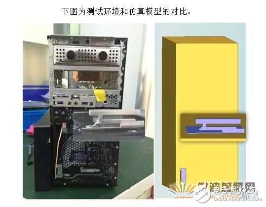
When using EMPro for workstation antenna simulation, the user not only uses the solid model of the antenna, but also considers the influence of the antenna carrier (chassis).
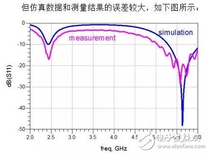
The test results and simulation results have obvious gaps in the insertion loss of the whole frequency band, and the test results have obvious resonance at the high end. Comparing the test object with the simulation model, the test object is fed with a long coaxial line, and the coaxial connector is not calibrated during the test; the simulation model uses the lumped port for feeding, and the feeder effect is not considered at all.
In order to make the simulation model as close as possible to the test object, a joint and a coaxial feed line can be added to the antenna. However, it is necessary to obtain the three-dimensional structure file and material properties of the test joint and the coaxial line, and the modeling and calibration work is costly.
Another method is to calibrate the test results, extract the model of the joint and the coaxial feeder, and add the effect to the simulation results. Quick and accurate extraction of joint and coaxial feeder models using AutomaTIc Fixture Removal technology.
Automatic Fixture Removal (AFR) calibration technologyAutomatic Fixture Removal (AFR) calibration technology is an easy way to extract accurate broadband fixture models. This calibration technique can be used in a variety of fixtures and interconnect structures such as adapters, chip packages, cables, PCB printed transmission lines, and interconnect structures such as vias. This calibration technique, like the traditional TRL calibration technique, has the same high-precision calibration performance and is easier to implement when making fixtures.
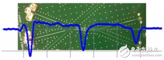
The figure below shows a through hole as a test board for the device under test. The through-hole structure is the object to be studied in the middle of the two-stage uniform transmission line. The two ends of the transmission line are SMA adapters for connecting to the network analyzer and measuring the S-parameters of the through-holes. In this example, the device under test that we care about is a through hole. For measurement, the through hole is in the middle of the clamp (the clamp includes an SMA connector and a transmission line connecting the through holes). As can be seen from the blue TDR response curve, the SMA adapter brings a non-negligible discontinuity and the transmission line is not completely uniform. Impedance fluctuations and transmission losses can be observed during transmission.
How to separate the measurement result of the DUT from the whole measurement result (the DUT and the fixture) is the problem to be solved by the AFR calibration technology.
The usual AFR technique is achieved when the fixtures on both sides of the device under test are mirror-symmetrical. In such a case, a calibration piece of the fixture is required to extract the S-parameter of the fixture. The calibration piece is in the form of directly connecting the clamps on both sides to form a straight-through structure that is twice the length of the single-sided clamp. This calibration is often referred to as a 2X straight-through reference fixture, as shown in the following figure:
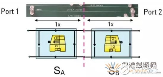
Although the one-sided fixture is not symmetrical, when two symmetrical fixtures are cascaded, the new 2X through-reference fixture calibration is mirror-symmetrical. Therefore, among the S parameters of the calibration piece obtained by the test, S11=S22, S21=S12, two known quantities can be obtained, but it is not enough to solve the three unknowns of the single-side fixture S parameter (S21A=S12A), as follows The figure shows.
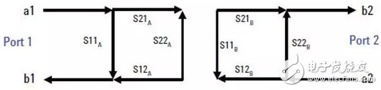
The AFR technology is based on the fact that the 2X straight-through reference fixture calibration component contains a uniform transmission line in the middle, and the S11A and S22B of the fixture can be extracted by using the time domain signal processing method. With an additional known amount, the S-parameters of the one-sided fixture can be solved uniquely.
Using the de-embedding technique, the influence of the fixture can be removed from the test results to obtain the S-parameter of the device under test; or the S-parameter of the fixture can be added to the simulation to facilitate comparison with the test results.
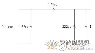
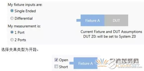
For antenna testing, it is more convenient to use single-ended AFR. The S2P file of the fixture can be obtained by solving the time gate and the signal flow diagram.
For AFR calibration, the coaxial connector and the open feeder are tested to obtain the S11 result. It can be seen that the resonance is very obvious above 6 GHz due to the frequency domain application range of the joint.
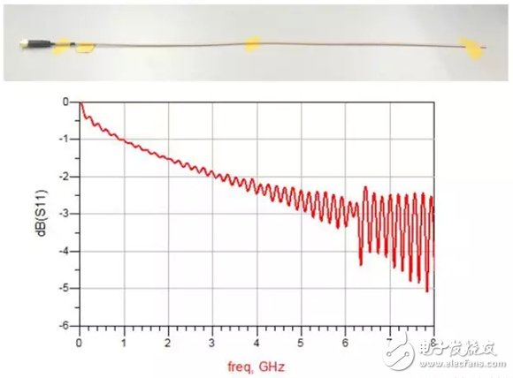
When performing AFR calibration, the S11 of the fixture is required to have no significant resonance and the test bandwidth is as wide as possible. For example, in this case, the de-embedding frequency is up to 6 GHz, but it is better to measure the clamp's DC to 50 GHz S11 because the physical size of the fixture is very small and the large test bandwidth can achieve higher resolution.
Import the test S11 results into the PLTS for a one-port AFR calibration:
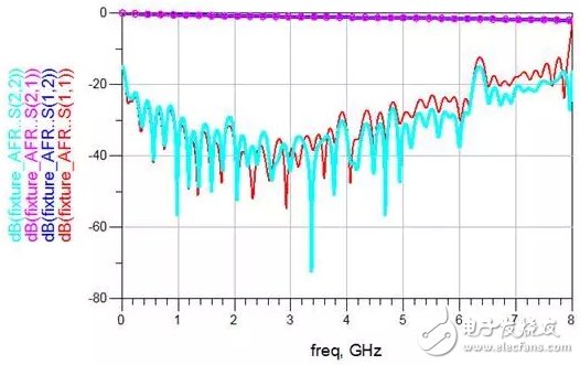
The S2P file of the fixture (SMA connector and coaxial cable) can be obtained using PLTS with the following response:
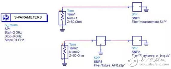
The S2P file of the fixture and the simulation result are cascaded and compared with the test results of the antenna.
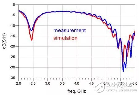
The comparison results are shown below. It can be seen that after considering the response of the joint and the coaxial line in the simulation, the obtained S11 result is very close to the test result.
Using the automatic fixture removal calibration technique, the S-parameters of the coaxial connectors and feeders in the antenna measurement system can be extracted without additional fixture fabrication. By cascading this S-parameter and the simulation model, the test results can be accurately approximated.
The resistance DC component magnetic core has strong resistance DC component ability, wide current range, few additional circuits and devices,strong reliability and insensitive to interference. Our company produces two kinds of resistance DC component magnetic cores: single core and composite core. The composite core adopts double core design, which has lower cost than cobalt based alloy. It has high permeability,low coercivity and loss,excellent performance on DC immune and temperature stability that can be widely used to the electronic watt-hour meter,resistance DC component transformer and electrical power system measurement.
Anyang Kayo Amorphous Technology Co.,Ltd. , https://www.kayoamotech.com