
In recent years, the term “embedded†has been increasingly mentioned by people, and embedded products have been applied to all walks of life. Embedded-related technologies such as embedded products and embedded system research have also been listed as the key directions for the development of the "10th Five-Year Plan".
Embedded system is defined as: Application-centric, computer-based, software and hardware can be tailored to meet the strict requirements of the function, reliability, cost, size, power consumption of special computer systems.
With the development of industrial automation, automation systems based on PLCs, SCMs and other devices have become more and more popular. They have spread almost all the fields of automation, and the corresponding human-computer interaction systems have also emerged. The industrial man-machine interface based on embedded technology is a dazzling star in the human-computer interaction system. High reliability, longevity, small size, high performance, multi-threading, multi-tasking, strong real-time and other features make the embedded industrial man-machine interface more and more popular among automation system integrators and automation equipment manufacturers. It can ideally and vividly display data information on PLCs, SCMs and other industrial equipments. It is powerful and easy to use. It is a bridge between the user and the machine as the upper equipment of PLC and other control equipment. This product is currently widely used in industrial automation systems, medical, financial and other industries automation equipment.
As more and more engineering projects use embedded human-machine interfaces, the demand for application software such as Supervisory Control and Data Acquisition (SCADA) for use with embedded hardware is also increasing. This is exactly what this article will discuss. Here the embedded monitoring system, its hardware is an embedded smart human-machine interface; its software is an embedded operating system, plus its own development of applications. The monitoring application is mainly introduced later in this article, focusing on the implementation of the communication part of the application.
Nowadays, a variety of embedded operating systems have been developed, such as Linux, VxWorks, WinCE.net, etc., and it is entirely possible to develop graphical and text-friendly and user-friendly applications on it to meet various requirements of the monitoring system. Just because embedded technology is a relatively new and leading technology, there are relatively few people involved, so this kind of application is still relatively small. The embedded monitoring system introduced in this article is an example.
2, the system compositionThe embedded monitoring system we have developed is the embedded intelligent industrial control man-machine interface (hereinafter referred to as the man-machine interface) developed by Shenyang Ludao Information Technology Co., Ltd. Its embedded industrial controller is GeodeX86 as the core processor, including network communication, data communication, large-size touch screen and liquid crystal display hardware platform, running WinCE operating system on it. Provide 20 common IO points for users, the physical layer supports ProfiBus and other field buses, supports 16-bit true color TFT LCD display, has 64MSDRAM memory, 64MFLASH flash memory, according to USB interface, 10/100MEthernet network communication interface, and serial port, parallel port, VGA port and other common interfaces.
The lower machine uses Japanese OMRON's PLC, or SIMENS PLC, or Schneider NEZA PLC, or Mitsubishi PLC of Japan, etc. The current popular PLC, of ​​course, temperature control table, SCM, intelligent module and other industrial field control equipment can also be.
The operation of the control object (such as a boiler, etc.) is controlled by the above-mentioned control devices (various PLCs, etc.); and the state of the control object is monitored using the human-machine interface and the application program developed thereon.
The man-machine interface operating system uses Microsoft's WinCE.net. WinCE.net is a compact, efficient, scalable operating system (OS) designed for a wide range of embedded systems and products. It is primarily intended for a wide range of embedded systems and products. Its multi-threaded, multi-tasking, fully preemptive features are specifically designed for limited resources. OEM developers can choose and tailor WinCE.net according to the characteristics of their own hardware components to configure a stable and efficient WinCE.net operating system and the corresponding SDK development package. In application, WinCE.net supports over 1000 public Microsoft Win32 APIs and several additional programming interfaces that users can use to develop applications. In addition, Microsoft has provided Microsoft eMbedded Visual C++ language similar to Visual C++ for the development of WinCE.net applications and supports MFC. Below we will introduce the details of the development process.
3, software processApplication development is done on a personal computer. The personal computer's operating system is WINDOWS2000. The application development platform is MicrosofteMbeddedVisualC++ integrated development environment.
You can also use the Microsoft-supplied Emulator during application development. With it, it is possible to perform program debugging even without a human-machine interface.
Development of the final generated executable file can be downloaded to the human-machine interface through the serial port or local area network using the download function provided by the Microsoft eMbedded Visual C++ development environment.
During work, PLCs and other industrial devices run their control programs, while the human-machine interface runs the downloaded executable file. Both communicate through the serial port, but the active party for communication is the human-machine interface. The man-machine interface sends a communication command to the PLC, etc. according to the monitoring requirements, and the PLC responds accordingly.
After the man-machine interface receives the response data from the PLC, it is displayed on the touch screen in the form of charts, animations, and texts for the user to observe. The data can also be stored, printed, and even transmitted to ERP and other management information systems.
If it is necessary to intervene on a PLC or a control object, it can also send commands or data to the PLC through touch keys or touch the mouse on the touch screen of the human-machine interface to achieve corresponding control.
The flow diagram of this application's execution is:
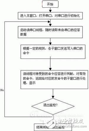
Figure 1 execution flow diagram
4, screen compositionThe general project monitoring screens are: text display, production process flow display (including animation, histogram display, etc.), alarm, personnel operation, trend curve and so on. Our system architecture is to do a program based on the main dialog. These different screens are then presented in sub-dialog boxes.
The main dialog box is responsible for initializing the serial port, opening the serial port, starting reading the serial port thread, etc.; and each sub dialog box sends various commands to the serial port on a regular basis or according to need, and reads the response of the command through the thread of the main dialog box, and then in the sub dialog box It is provided to users in certain forms for monitoring on-site operations. The main technology here is serial communication. Below we focus on the realization of communications.
5, communication to achieveThe serial port provided by the man-machine interface is in line with the common standard. Serial communication under WinCE.net is the same as serial communication under Windows. Are all applications
Instead of directly controlling the hardware, data transfer is performed through a device driver provided by the operating system.
WinCE.net is Win32 programming. The serial port is handled as a file in Win32 and is not directly operated on the port. For serial communication, Win32 provides the corresponding file I/O functions and communication functions.
However, it should also be noted that the API functions supported by WinCE.net are only a subset of the Window API functions. Some Windows, WinCE.net may not be able to use. At the same time, the WinCE.net character set is similar to Windows NT and unlike Windows 9x, it is based on Unicode. This is also the place where programmers who go from WINDOWS to WinCE.net encounter most problems during the development process. In addition, some of the commonly used communication controls under Windows such as MSComm cannot be used correctly under WinCE.net.
The monitoring system uses API functions to achieve serial communication. The following sub-topics introduce serial communication and the implementation of the entire system.
5.1 Open the Serial Port
The first is to open the serial port, which is the first step in serial communication. Its code is:
BOOLCMainDlg::OnInitDialog()
{
. . . . . .
m_hComm=CreateFile(_T("COM1:"), GENERIC_READ|GENERIC_WRITE,0,NULL,OPEN_EXISTING,0,0);//Open the operation of the serial port, need to pay attention
The WinCE.net system is slightly different from the Windows system. WinCE.net requires a colon after the serial port.
SetupComm(m_hComm,1024,1024);//Initialize serial port input, output buffer parameters;
SetCommState(m_hComm,&m_dcb);//Configure the serial port parameters; m_dcb is a good parameter structure;
. . . . . .
SetCommTImeouts(m_hComm, &TImeout);//Set communication timeout parameters;
PurgeComm(m_hComm,PURGE_TXCLEAR|PURGE_RXCLEAR);
/ / Clear input, output buffer characters, in order to start accepting data, ready to enter the monitoring state;
. . . . . .
}
5.2 Reading Serial Port Threads
The second is to start reading the serial port thread, which allows the serial port program to continuously run in the background without affecting the work of the foreground program. The code related to this is:
BOOLCMainDlg::OnInitDialog()
{
. . . . . .
ReadFile (m_hComm, inBuffer+iBufLen, INBUFFERLEN-iBufLen, &dwBytes, NULL);//Read data from the serial port;
iBufLen+=dwBytes;
For(inti=â€0â€;i{
If (inBuffer [i] == "") / / to connect the device to OMRONPLC as an example, the communication protocol specifies that the response should end with "";
inBuffer[i]=0;//string end flag;
Switch(m_iDlgType)//m_iDlgType is a flag variable representing different dialogs;
{
Case subdialog 1 flag:
Sub-dialog 1.ProcData(inBuffer,i);//The processing of the command response in different dialogs, ProcData is the function name;
Break;
. . . . . .
}
. . . . . .
}
5.3 Each Sub-Dialog Box Sends Write Commands
Each sub-dialog box, in the form of a timer, periodically sends commands to the PLC as needed. Taking OMRON PLC as an example, when sending a command, according to the communication protocol of OMRON PLC, it is also necessary to add a check code to the sent command string. The program code is:
Void subdialogue1::OnTimer(UINTnIDEvent)
{
. . . . . .
Strcpy(m_szC
Md, "@00RR00000001");//OMRONPLC command string;
GenXor(m_szCmd,result);//Checksum calculation, call GenXor function;
Sprintf(szTailer, "%02X*", result);//OMRONPLC communication protocol ends with "*";
Strcat(m_szCmd,szTailer);//form a complete communication protocol command string;
WriteFile(m_hComm,m_szCmd,strlen(m_szCmd),&dwWriten,NULL);
// Write the command string to the serial port;
. . . . . .
}
The following is the code for the checksum called above:
voidGenXor(LPCSTRstrSource, char&result) // Performs an XOR operation for the function that computes the checksum:
{
Result=0;// is the initial value of the check code assignment;
Intlen="strlen" (strSource);//The length of the command protocol string;
For(inti="0";iresult^=strSource[i];// bitwise XOR;
}
5.4 Display Interface Processing
Finally, the data read by the thread is read and processed by the corresponding sub-dialog. These data should be analyzed and expressed in animations, histograms, trend curves, etc. Take OMRON PLC connected as an example, the code is:
Void subdialogue1::ProcData(char*buffer,intlen)
{
. . . . . .sscanf(buffer+7,“%04Xâ€,&wData);//According to the OMRONPLC command specification, the data needed from the reply will be taken out into the variable wData;
. . . . . . . // The value of the obtained variable is processed as required, for example, displayed in a sub-dialog box in the form of text or animation;
}
In the interface processing, there are some techniques, such as animation display, you can use a timer to control the rotation of the picture display. (In this system animation is displayed via the CbitmapButton control.)
Switch(m_iImage)//m_iImage is a defined animation display flag;
{
Case1:// displays the first picture and sets the animation display flag to 2;
CBitmapButton control variable. LoadBitmaps (image flag 1);
m_iImage=2;
Break;
Case2:// display the second picture and set the animation display flag to 1;
CBitmapButton control variable. LoadBitmaps (image flag 2);
m_iImage=1;
Break;
}
When real-time curves are displayed, a circular array is used to open up a certain amount of space in the memory so that the read numbers form a circular array and are dynamically displayed on the interface.
This system uses 20 analog quantities as an array size, that is, the real-time trend curve always shows 20 points of information, but it looks very dynamic because of the use of a cyclic array technology.
Void subdialogue class::looping array function (intiValue)//iValue is the valid data parsed from the command response;
{
Intindex=(m_iBegin+m_iCount)%20;//Calculate the index of loop array, starting from 0 initially;
m_aryValue=iValue;//Assignment of a loop array;
m_iCount++;//The number of loop arrays plus 1;
If(m_iCount(20)) // Judgment whether the number is more than 20, if so, start the next array subscript from 1, and so on;
{
m_iCount=20;
m_iBegin=(m_iBegin+1)%20;
}
. . . . . .
}
Communication is the key to this system. Our practice proves that the above four steps are the basic points for realizing the entire monitoring system.
6 ConclusionIn short, the basic architecture of the monitoring system software can be visualized with the following diagram:

Figure 2 The basic architecture of the monitoring system software
With the rise of embedded operating systems, developers of configuration software have also developed an embedded version of the configuration software. But in
In practical applications, we found that there are many companies whose production control processes are relatively fixed and the number of human-machine interfaces required is relatively large. For them, according to the methods described here, they are developed according to the characteristics of the company's own production process, and provide The final operating system is given to the user, which does not require the user to perform secondary development of the configuration. Such systems are suitable for such users in terms of time, price or performance. The system has been tested and operated on the LEODO embedded industrial control man-machine interface developed by the company. It proves that the operating speed is relatively fast and stable. The effect is very good, more suitable for industrial use. Of course, the LEODO brand man-machine interface also has a set of concise and practical screen resource-rich ET configuration software. Users can decide whether to use high-level language development or configuration software development according to the actual situation.
In short, it can be seen that the man-machine interface uses Microsoft eMbedded C++ to develop applications, and there are many similarities to the development of programs using Microsoft Visual C++ under the Windows system. With this software and hardware platform, most users can fully develop applications that suit their needs.
Multi-Port Type-C Charger,Desktop Usb Charging Station,Usb Fast Charging Station,Multi Device Charger Organizer
shenzhen ns-idae technology co.,ltd , https://www.best-charger.com