
Although many descriptions of modulation portray it as a multiplication process, the actual situation is more complicated.
First, for the sake of clarity, if the signal Acos and the unmodulated carrier cos(ωt) are applied to the two inputs of the ideal multiplier, we will get a modulator. This is because the two periodic waveforms Ascos(ωst) and Accos(ωct) are applied to the input of the multiplier (assuming a scale factor of 1 V for analysis), and the resulting output is:
V o (t) = 1â„2A s A c [cos(( ω s + ω c )t) + cos(ω s – ω c )t))]
If the carrier Accos(ωct) has an amplitude of 1 V (Ac = 1), the equation is further simplified to:
V o (t) = 1â„2A s [cos(( ω s + ω c )t) + cos((ω s – ω c )t)]
But in most cases, the modulator is a better circuit to perform this function. The modulator (also known as the mixer when changing the frequency) is closely related to the multiplier.
The output of the multiplier is the instantaneous product of its input.
The output signal of the modulator is a modulator wherein one input (referred to as input signal) and the other input signal symbols (called carrier input) the instantaneous product.
Figure 1 shows two modeling methods for the modulation function:
Used as an amplifier to switch positive gain and negative gain through the comparator output on the carrier input;
Used as a multiplier and placed a high gain limiting amplifier between its carrier input and one of its ports.
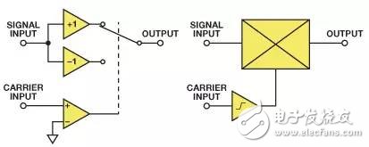
Figure 1. Two modeling methods for modulation functions
Both architectures can be used to form the modulator, but the switching amplifier architecture (used in the AD630 balanced modulator) runs slower. Most high speed IC modulators have a translinear multiplier (based on Gilbert cells) and have a limiting amplifier on the carrier path to overdrive one of the inputs. The limiting amplifier may have high gain, allowing low-level carrier input - or with low gain and clean limiting characteristics, requiring relatively large carrier inputs to operate properly.
For some reason, we use a modulator instead of a multiplier. Both ports of the multiplier are linear, so any noise or modulated signal from the carrier input is multiplied by the signal input to reduce the output; at the same time, the amplitude variation of the modulator carrier input can be ignored in most cases. The second-order characteristic causes the amplitude noise of the carrier input to affect the output, but the best modulator will minimize this effect and is therefore beyond the scope of this article. A simple modulator model uses a carrier-driven switch.
The (ideal) open-circuit switch has an infinite resistance and zero thermal noise current, and the (ideal) closed-circuit switch has zero resistance and zero thermal noise. Therefore, although the modulator's switching is not ideal, the modulator still has lower internal noise than the multiplier. In addition, a high-performance, high-frequency modulator similar in design and manufacture is easier than a multiplier.
Like the analog multiplier, the modulator multiplies the two signals; however, unlike the analog multiplier, the multiplication of the modulator is non-linear. When the polarity of the carrier input is positive, the signal input is multiplied by +1; and when the polarity is negative, it is multiplied by –1. In other words, the signal is multiplied by a square wave at the carrier frequency.
A square wave with a frequency of ωct can be represented by the odd harmonics of the Fourier sequence:
K[cos(ωct) – 1/3cos(3ωct) + 1/5cos(5ωct) – 1/7cos(7ωct) + ...]
The sequence is summed: [+1, –1/3, +1/5, –1/7 + ...] is π/4. Therefore, the K value is 4/π, so that when a positive DC signal is applied to the carrier input, the balanced modulator can be used as a unity gain amplifier.
The carrier amplitude is not important, as long as it is large enough to drive the limiting amplifier; therefore, the output produced by the modulator driven by the signal Ascos (ωst) and the carrier cos(ωct) is the product of the signal and the square of the carrier:
2As/π[cos(ω s + ω c )t + cos(ω s – ω c )t –
1/3{cos(ω s + 3ω c )t + cos(ω s – 3ω c )t} +
1/5{cos(ω s + 5ω c )t + cos(ω s – 5ω c )t} –
1/7{cos(ω s + 7ω c )t + cos(ω s – 7ω c )t} + ...]
The output contains the difference between the sum of the frequencies of the following terms and the frequency: all odd harmonics of the signal to the carrier, signal and carrier. There is no even harmonic product in the ideal perfect balanced modulator. However, in a real modulator, the residual offset of the carrier port results in a low-order even harmonic product. In many applications, a low pass filter (LPF) filters out higher harmonic product terms. Remember that cos(A) = cos(–A), so cos(ωm – Nωc)t = cos(Nωc – ωm)t, and there is no need to worry about the “negative†frequency. After filtering, the modulator output can be calculated as follows:
2As/π[cos(ω s + ω c )t + cos(ω s – ω c )t]
It is identical to the expression output by the multiplier, except that the gain is slightly different. In practical systems, the gain is normalized using an amplifier or attenuator, so there is no need to consider the theoretical gain of the different systems here.
In a simple application, it is clear that using a modulator is better than using a multiplier, but how do you define "simple"?
When the modulator is used as a mixer, the signal and carrier inputs are simple sine waves with frequencies equal to f 1 and fc, respectively. The unfiltered output contains the frequency sum (f 1 + f c ) and the frequency difference (f 1 – f c ), and the frequency and frequency difference between the signal and the carrier odd harmonics (f 1 + 3f c ), (f 1 – 3f c ), (f 1 + 5f c ), (f 1 – 5f c ), (f 1 + 7f c ), (f 1 – 7f c ). After LPF filtering, it is expected that only the fundamental terms (f 1 + f c ) and (f 1 - f c ) are obtained.
However, if (f1 + fc) > (f1 – 3fc), the simple LPF cannot be used to distinguish between the fundamental and harmonic terms because the frequency of a harmonic term is below a certain fundamental term. This is not a simple case and therefore needs further analysis.
If the signal is assumed to contain a single frequency f1, or if the signal is more complex and distributed in the frequency bands f1 to f2, then we can analyze the output spectrum of the modulator, as shown in the following figure. Assuming that the perfectly balanced modulator has no signal leakage, carrier leakage, or distortion, the output contains no input terms, carrier terms, and spurious terms. The input is shown in black (or in light gray in the output image, even if it doesn't actually exist).
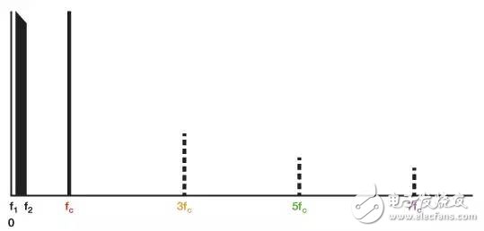
Figure 2. Input spectrum showing signal input, carrier and odd carrier harmonics
Figure 2 shows the inputs—signals in the f1 to f2 band and the carrier at frequency fc. The multiplier does not contain the following odd carrier harmonics: 1/3 (3fc), 1/5 (5fc), 1/7 (7fc)..., indicated by dashed lines. Note that the decimals 1/3, 1/5, and 1/7 represent amplitude, not frequency.
Figure 3 shows the output of the multiplier or modulator and the LPF with a cutoff frequency of 2fc.
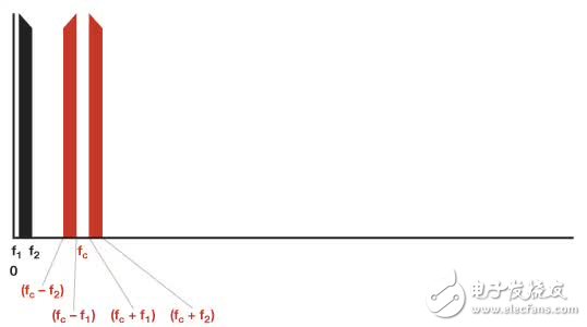
Figure 3. Output spectrum using a multiplier or modulator of the LPF
Figure 4 shows the unfiltered modulator output (but does not contain harmonic terms above 7fc).
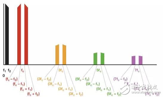
Figure 4. Unfiltered modulator output spectrum
If the signal bands f1 to f2 are located in the Nyquist band (DC to fc/2), an LPF with a cutoff frequency higher than 2fc will have the modulator have the same output spectrum as the multiplier. The situation is more complicated if the signal frequency is higher than the Nyquist frequency.
Figure 5 shows what happens when the signal band is just below fc. It is still possible to separate the harmonic term and the fundamental term, but at this point an LPF with steep roll-off characteristics is used.
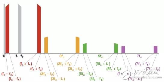
Figure 5. Output spectrum when the signal is greater than fc/2
Figure 6 shows that since fc is in the signal passband, the harmonic term is superimposed (3fc – f1) < (fc + f1), so the fundamental term can no longer be separated from the harmonic term by the LPF. The desired signal must now be selected by a bandpass filter (BPF).
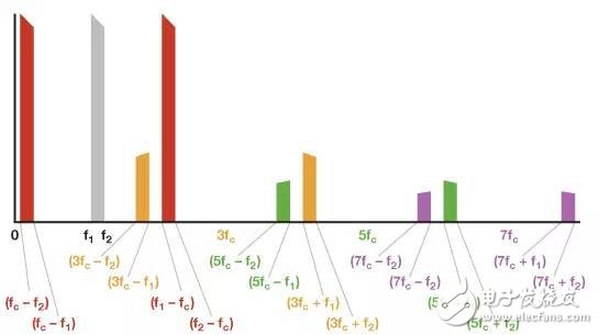
Figure 6. Output spectrum when the signal exceeds fc
Therefore, although modulators are superior to linear multipliers in most frequency conversion applications, their harmonics must be considered when designing the actual system.
The utility model relates to a medical atomization treatment and humidifying device belonging to the technical field of medical equipment and household appliances.
Professional Medical Atomization manufacturer is located in China, including Medical Vape,Dose Control Vape Pen,Supersonic Wave Vape, etc.
Medical Atomization,Medical Vape,Dose Control Vape Pen,Supersonic Wave Vape
Shenzhen MASON VAP Technology Co., Ltd. , https://www.e-cigarettefactory.com