
With the increasingly prosperous market of general-purpose inverters, their annual usage has increased rapidly. However, there are still some unsatisfactory places for inverters under different operating conditions, which leads to shortened service life and installation and commissioning of auxiliary equipment. The workload of routine maintenance and repairs has also increased accordingly, causing major direct and indirect economic losses to users. The application environment, electromagnetic interference and anti-jamming of the inverter, and the quality of the power grid are analyzed. The problems that should be noted when using the inverter and the corresponding suggestions for improvement are proposed. It is believed that this will significantly improve the service life of the inverter. effect.
1 Effect of electromagnetic interference on the inverter
In the modern industrial control system, microcomputer or PLC control technology is often used. In the process of system design or transformation, attention must be paid to the interference of the inverter to the microcomputer control board. The external interference source of the frequency converter is shown in Fig. 1. Because the user's own designed microcomputer control board has poor general technological level and does not comply with the EMC international standards, the conduction and radiation interference generated after the adoption of the frequency converter often lead to abnormal operation of the control system. Therefore, the following necessary measures need to be taken.
1) Good grounding. The grounding wire of a strong electrical control system such as a motor must be reliably grounded through the ground busbar. The shielded ground of the microcomputer control board should be grounded separately. For some serious interference situations, it is recommended to connect the sensor and I/0 interface shield with the control board control ground.
2) Add EMI filter, common-mode inductance, high-frequency magnetic ring, etc. to the input power of the microcomputer control board, which can effectively suppress conducted interference. In addition, in the case of severe radiated interference, such as the presence of GSM or PHS base stations, a metal mesh shield can be added to the computer control panel for shielding. / F)
3) Install EMI filter on the input end of the inverter, which can effectively suppress the conduction interference of the inverter to the power grid. Adding input AC and DC reactors can increase the power factor, reduce harmonic pollution, and have a good comprehensive effect. When the distance between some motors and the inverter exceeds 100 m, an AC output reactor must be added on the inverter side to solve the leakage current protection caused by the distribution parameters of the output conductors to the ground and reduce the radiation interference to the outside. An effective method is to use steel pipe threading or shielded cable method and reliably connect the steel pipe shell or cable shield to the earth. It is worth noting that when the AC output reactor is not added, if the method of pipe threading or shielded cable is adopted, the distributed capacitance of the output to the ground is increased, and over-current may occur easily. Of course, one or several methods are generally adopted in practical applications.
4) Electrically shield and isolate the analog sensor detection input and the analog control signal. During the design of the control system composed of inverters, it is recommended not to use analog control as much as possible, especially when the control distance is greater than 1m and the control cabinet is installed. Because the frequency converter generally has multi-stage speed setting, switching frequency input and output, can meet the requirements. If it is necessary to use analog control, it is recommended to use shielded cables, and to achieve a remote ground at the sensor or inverter side. If the interference is still serious, you need to implement DC/DC isolation measures. Can use the standard DC/DC module, or adopt the v/f conversion optical isolation, and then use the frequency setting input method.
The impact of the work environment
In actual application of frequency converters, domestic customers install a frequency converter directly at the industrial site to reduce costs, except for a few dedicated customers. The work site generally has problems of large dust, high temperature, and high humidity, as well as metal dust, corrosive gases, and the like in the aluminum industry. Therefore, corresponding countermeasures must be made according to the site conditions, as shown in Figure 2.
1) The inverter should be installed inside the control cabinet.
2) The inverter is preferably installed in the middle of the control cabinet; the inverter shall be installed vertically and directly above and below to avoid installation of large components that may block the exhaust and air intake.
3) The minimum distance between the upper and lower edges of the inverter and the top, bottom, or bulkheads of the control cabinet, or the large components that must be installed, should be greater than 300 mm.
4) If the special user needs to take out the keyboard during use, the keyboard hole of the inverter panel must be sealed tightly with tape or replaced with a dummy panel to prevent dust from entering the inverter.
5) When using frequency converters in dusty places, especially in places with multiple metal dusts and flocs, the overall requirements for control cabinets are totally sealed, and air inlets and outlets are specially designed for ventilation; the top of control cabinets should have protective nets and protective tops. Cover the air outlet; the bottom of the control cabinet should have bottom plate, air inlet, inlet hole, and dustproof net.
6) Most printed circuit boards and metal structural parts inside the inverter manufacturers are not subjected to special treatment against moisture and mildew. If the inverter is under a harsh working environment for a long time, the metal structural parts will be easily rusted. In the case of high-temperature operation, the conductive copper busbars will become even more rusty. Corrosion will damage the tiny copper conductors on the microcomputer control board and the driver power board. Therefore, for the application to damp and corrosive gases, the internal design of the inverter used must have basic requirements. For example, the printed circuit board must be coated with three anti-paints, and the structural parts must be treated with nickel-chromium plating. Process. In addition, other positive, effective, and reasonable measures against moisture and corrosion are also needed.
The influence of grid quality on frequency converter
In the impact load such as welding machine, arc furnace, rolling mill and other occasions, the voltage often flicker; in a workshop, when there are multiple frequency converters and other capacitive rectified load in the work, the harmonics generated by it have a very good quality for the power grid. Severe pollution also has a considerable destructive effect on the equipment itself. If it is light, it cannot be continuously operated normally, and it causes damage to the input circuit of the equipment. The following measures can be taken.
1) In the case of impact loads such as welding machines, electric arc furnaces, rolling mills, etc., users are advised to increase the static compensating device and improve the power factor and quality of the power grid.
2) In the workshop where the inverter is relatively concentrated, it is recommended to use centralized rectification and DC common bus power supply. It is recommended that users use 12-pulse rectification mode. The advantages are low harmonics and energy saving, especially suitable for frequent starting and braking, and the motor is in the occasion of both electric operation and power generation operation.
3) The passive LC filter is installed on the input side of the inverter to reduce input harmonics, improve power factor, and has high reliability and good effect.
The source PFC device is installed on the input side of the inverter, which is the best, but the cost is higher.
24HR Electronic Timer socket with photocell.
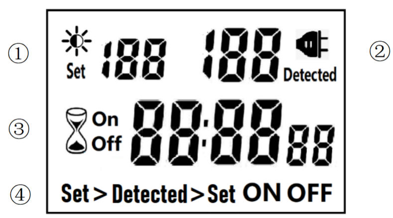
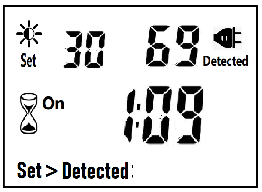
â‘ Light intensity setting
â‘¡ Light intensity detection
â‘¢ Countdown Timer ON & OFF
â‘£ 4 MODES:
Set > Detected: When the light intensity detection value is less than the set value, switch ON or OFF.
Detected > Set: When the light intensity detection value is greater than the set value, switch ON or OFF
ON : Always ON
OFF : Always OFF
NOTED:
1. The light intensity displayed by this machine is not the standard light intensity value (Lux), only the relative light intensity value.
2. The light intensity value is affected by the placement position and direction. Please determine the position first and then set it according to the actual light intensity detected. If you change the position or change the orientation, you need to reset the light intensity setting value suitable for the new position.
3. This product has built-in rechargeable battery. If it is not connected to AC for a long time, you need to connect the power supply to charge until the LCD can display normally.
MANUAL OPERATION
1. Press [UP" or [DOWN" to set the LUX value.
2. Press the [SET" key to start setting, and the P1 settable items will be flashed.
3. Press [UP" or [DOWN" to adjust the value.
4. Press [SET" key again to exit setting or enter next setting for countdown timer.
5. Repeat the [SET" key to start setting, and the P2 & P3 settable items will be flashed.


6. Press the [FUN" key to switch the working state in the following:
Set > Detected -> Detected > Set -> ON -> OFF
Set > Detected: Automatically switches when the detected ambient light intensity is darker than the set value
Detected >Set: Automatically switch when the detected ambient light intensity is brighter than the set value
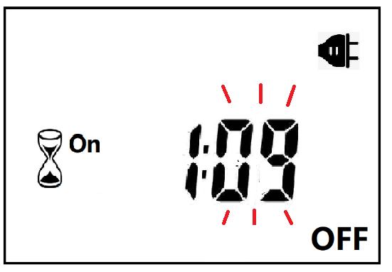
When the brightness meets the setting conditions, the countdown starts as below:
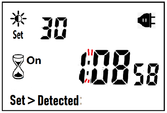
Note:when the countdown is ON, the detected value is not displayed.
When the brightness does not meet the setting conditions, the countdown stops and waits:
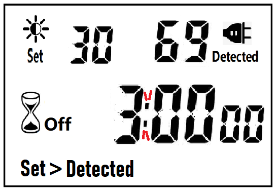
After the countdown ON is reduced to 0, the countdown OFF starts immediately and the power is OFF.
After the countdown OFF is reduced to 0:
A. If the light intensity meets the set conditions, a new round of countdown will be started;
B. If the light intensity does not meet the set conditions, keep the power off and wait for the light to meet the conditions before turning on automatically.
NOTE:
1. If the power is cut off while the countdown is running, the countdown will be terminated immediately and the relay output will be off. After the power is turned on again, a new round of brightness detection will start.
2. Modifying the brightness value in the countdown operation will not affect the current countdown operation. After the off time of the current countdown, the new brightness setting value will take effect.
3. In the countdown on operation, change the setting value of the countdown on, this countdown will still be timed according to the original setting value; the new setting value will take effect when the next countdown on starts.
4. In the countdown off operation, change the setting value of countdown off, this countdown will still be timed according to the original setting value; the new setting value will take effect when the next countdown off is started.
NOTE: the brightness setting value, countdown ON or countdown OFF, any one of which is equal to 0, cannot be switched ON or OFF automatically.
Manual Control
When ON or OFF is displayed, it means that the power supply remains ON or OFF, as shown in the figure below:

Power Detection and Standby Mode
With AC power supply, the icon ![]() lights up and works normally.
lights up and works normally.
When there is no AC power supply, the icon ![]() goes out, the brightness is not detected at this time, and the system enters the standby mode.
goes out, the brightness is not detected at this time, and the system enters the standby mode.
Photocell Timer, photocell timer socket, photocell sensor, photocell sensor socket, sensor plug, sensor switch socket, digital photocell timer, digital sensor timer
NINGBO COWELL ELECTRONICS & TECHNOLOGY CO., LTD , https://www.cowellsocket.com