Power Quality: A voltage, current, or frequency deviation that causes a consumer to malfunction or not function properly, including voltage deviations, voltage fluctuations and flicker, three-phase imbalance, transient or transient overvoltage, and waveforms. Distortion and harmonics, voltage sag and short-term interruptions.
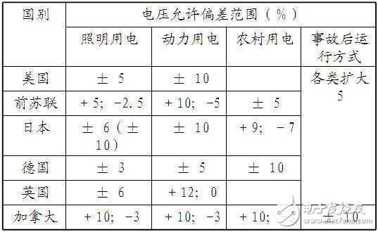
Second, the voltage deviationGB: Power supply voltage deviation (GB 12325-1990) (GB/T 12325-2008)
Voltage deviation: In normal operation mode, the difference between the actual voltage of a node and the nominal voltage of the system to the nominal voltage of the system is called the voltage deviation of the node.
National standard requirements:
1, the sum of positive and negative deviations of 35kV and above is 10%
2, 20kV and below ≤ ± 7%
3, 220V single phase + 7% ~ -10%
4. The short-circuit capacity of the power supply is small, the power supply distance is long, and the user who has special requirements on the power supply voltage is determined by both the power supply and the power.
Control measures: The hazard does not have to be said, and it has great harm to the equipment and the stability of the power angle.
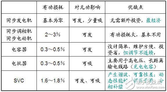
1) Configure enough reactive power supply
Principle: Partition, stratification, sub-substation compensation, to achieve local balance of reactive power, and leave enough spare capacity.
2) System voltage regulation
In the system, some key busbars are selected as voltage monitoring points. If the voltage deviation of the voltage monitoring point can be controlled within the allowable range, the voltage and load voltage of other points in the system can basically meet the requirements. These voltage monitoring points are called voltage hub points. The voltage central point generally selects the high-voltage busbar of the power plant with large installed capacity in the system, the low-voltage busbar of the substation with large capacity, and the generator busbar with a large number of local loads.
Generator voltage regulation: first considered, shortcomings: This method can only meet the voltage regulation requirements of power plant area load, and can not meet the requirements for the load through multi-level voltage transmission.
Transformer voltage regulation: The premise of this voltage regulation method is that the reactive power of the system is sufficient. This method only changes the reactive power distribution of the power system. In systems with sufficient reactive power, the use of on-load tap-changers should be promoted.
As for the automatic control of the reactive voltage, it is another level.
Engineering case:
In the usual power quality analysis report, reactive power calculation is a key point (the other is harmonic calculation).
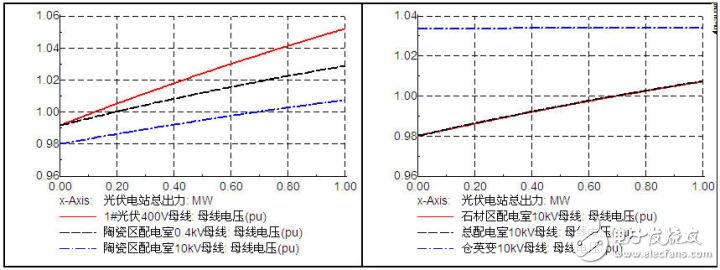
The resulting reactive compensation configuration scheme should come from two aspects. One is the theoretical calculation, which is based on the electrical parameters of the similar line length and the number of boxes, and calculates how much reactive power needs to be configured. The other is the simulation calculation, which is calculated in size. In the mode, the condition of the bus voltage of the relevant component is as shown below.
National standard: voltage fluctuation and flicker (GB 12326-2000) (GB/T 12326-2008)
Voltage fluctuation: A periodic voltage variation in which the amplitude of the fluctuation does not exceed 10%. Often, this change is much smaller than most electrical equipment sensitive limits, so operational problems only occur in a few cases. The main cause of voltage fluctuations is the power shock fluctuation load. (The picture below shows the voltage fluctuation caused by the electric arc furnace)
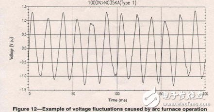
In the national standard, the limit value of voltage fluctuation is set for a typical electric arc furnace load.
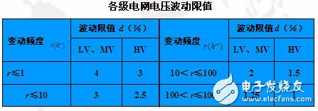
Voltage flicker: Flicker is a harmful result caused by voltage fluctuations. It refers to the subjective visual sensation of human fluctuations. It is not an electromagnetic phenomenon. Strictly speaking, the term voltage flicker is conceptually confusing. There are also some measurement indicators here, but generally not easy to quantify, not much consideration.
Control measures:

(1) Increase the voltage level of the power supply to increase the short-circuit capacity of the common connection point with the power grid, so that the impact on the power grid is limited to the allowable range;
(2) The SVC (SVG) device is used to limit its multiple indicators to the allowable range.
The amount of reactive power variation is the main factor causing the voltage fluctuation and flicker of the electric arc furnace, so maintaining the reactive power of the system is the fundamental method to improve and suppress voltage fluctuations and flicker.
Due to the fixed impedance, the conventional shunt capacitor bank not only cannot dynamically track the load reactive power change but also adjusts the reactive power compensation, and the harmonics are seriously amplified, so it cannot be used in the occasions of voltage fluctuation and large flicker. The static var compensator (SVC) is automatically compensated according to the demand of reactive power. The so-called static var compensator static means that it has no mechanical moving parts, but its compensation is dynamic, that is, according to the demand of reactive power or voltage change. Automatic tracking compensation.
SVC consists of controllable inductors, fixed or variable capacitor branches in parallel. The engineering applications are: saturated reactor (SR), thyristor controlled reactor (TCR), thyristor switching capacitor (TSC) and thyristor controlled High impedance transformer (TCT). The TCR type SVC is the most widely used.
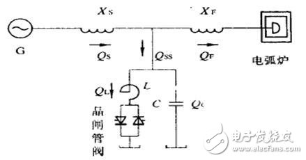
SVG (statcom): The voltage source type inverter is better. The amplitude of the DC side capacitor voltage and/or the modulation ratio of the converter can be adjusted to control the amplitude of the AC output voltage of the converter, thereby changing the output current of the device. Polarity (capacitive or inductive) and size, for the purpose of continuously controlling the polarity and size of the output reactive power.
SVG is superior to SVC in terms of reactive power control capability, reactive power compensation response speed, capacity required for equivalent compensation effects, floor space, loss, and output reactive power. Moreover, in recent years, the price gap between the two has become smaller, and the domestic SVG technology has matured.
Fourth, waveform distortion and power harmonicsNational standard: voltage fluctuation and flicker (GB 12326-2000) (GB/T 12326-2008)
Waveform Distortion: Waveform distortion is caused by nonlinear equipment in the power system, and the current flowing through the nonlinear device is not proportional to the voltage applied to it.
Power Harmonics: Any periodic distortion waveform can be represented by the sum of sinusoidal waveforms. The component whose frequency is an integer multiple of the fundamental frequency is called harmonic (if the power frequency of China's power system is 50Hz, the fundamental wave is 50Hz, The second harmonic is 100 Hz, the third harmonic is 150 Hz, etc.), the component whose frequency is an integer multiple of the fundamental frequency is called harmonic, and the sum of a series of sinusoidal waveforms is called the Fourier series.
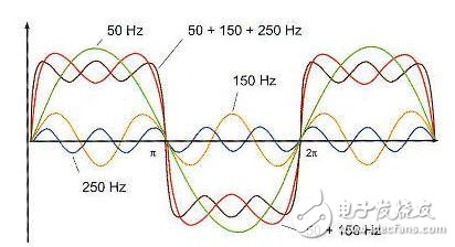
Under certain power supply system conditions, some electrical loads will have non-integer multiples of periodic current fluctuations, not fractional harmonics of the fundamental multiple of the frequency. The subharmonic refers to the component whose frequency is lower than the fundamental frequency of the power frequency.
The transient process contains high-frequency components, but the harmonics are two completely different phenomena. The power system has high-frequency characteristics only after being suddenly disturbed, but these frequencies are not harmonics, and the base Wave frequency is irrelevant.
National standard requirements:
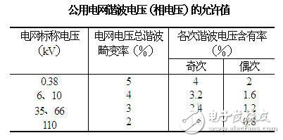
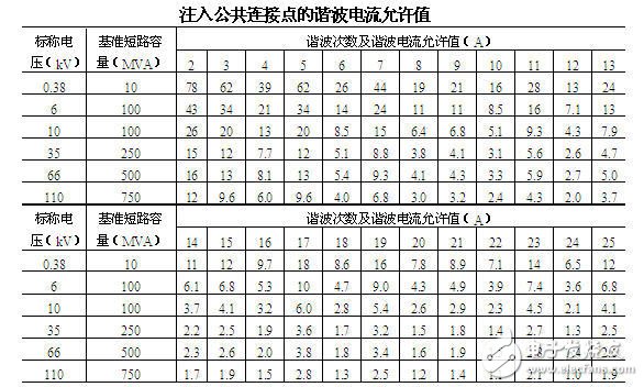
The calculation of the ordinary harmonics is generally calculated by the power software. Of course, it can be calculated by the formula.
Harmonic sources: The main harmonic source in traditional power systems is power transformers, the most important harmonic source in contemporary power systems - nonlinear power electronics.
harm:1) System angle, harmonics will lead to some abnormal phenomena: First, the ultra-high voltage long line, if the harmonic current is large, the submerged power arc will be delayed, the single-phase reclosing may fail, expand the accident, the arc suppression coil This problem also exists in the grounded system. Second, when the harmonic component is large, it may cause protection misoperation or rejection. For example, the zero-order third harmonic is too large, which may cause the grounding protection to malfunction. The third is the measurement and measurement error. Especially for the meter for zero-crossing detection phase, it is more serious.
2) Harmonics cause additional loss of equipment and reduce efficiency. Especially for the impact of the capacitor bank, as the frequency increases, the dielectric loss will increase significantly; for the transmission line, due to the high harmonic frequency and skin effect, the line resistance will increase, thus causing the accessory line loss; At the same time, transformers and motors, etc., will cause some additional copper and iron losses, resulting in local overheating.
3) Accelerate insulation aging and greatly shorten equipment life. Under the action of harmonics, the physical process of insulation aging is obviously intensified, which is very harmful to cables and capacitors.
4) Local series or parallel resonance may be generated and the harmonic level is amplified. As a result, the devices in the harmonic branch are damaged by overvoltage or overcurrent. For example, after the reactor of the reactance rate is connected in series in the capacitor device, the harmonics of the power grid 5 times or more can be suppressed, but the harmonics of 5 times or less are amplified.
5) Harmonics interference with the communication system. If the harmonic frequency is close to the carrier frequency, the power line carrier communication and the telecontrol device signal transmission will be interfered to some extent. In addition, electromagnetic, electrostatic and conductive coupling paths will also interfere with the parallel laying communication lines.
Control measures:The suppression or mitigation measures of power harmonics can usually be divided into preventive measures and compensatory measures.
Preventive measures: 1) Power supply equipment such as capacitors, transformers, generators, etc. take measures to reduce harmonics in design, manufacture, planning, configuration, etc.; 2) limit power harmonics by increasing the number of pulsations of the rectifier or by using controlled rectifier The main source of the harmonics of the rectifier.
Compensatory measures: 1) application of the filter; 2) changing the feeder parameters, using the feeder reconstruction or capacitor to change the installation position to avoid resonance.
Passive power filter: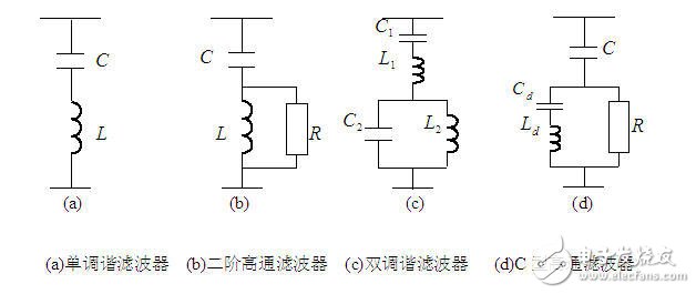
For high-capacity harmonic filtering projects, several sets of single-tuned filters (or dual tuning) are often used in conjunction with a set (or sets) of high-pass filters.
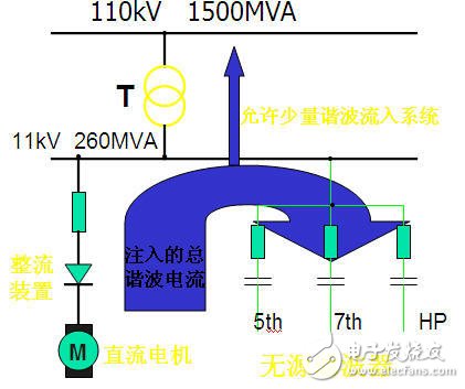
After the filter parameters are initially determined, the final determination of the filter parameters needs to be corrected in combination with the filtering effect and the reactive power compensation requirements.
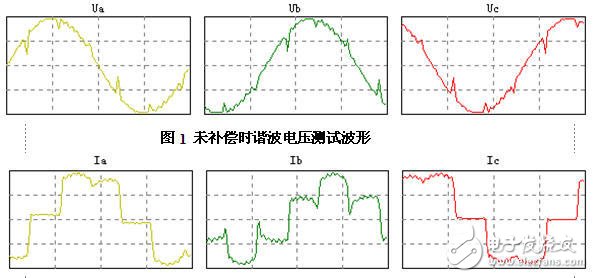
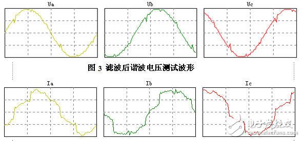
The passive filter device is the most widely used harmonic suppression method at present. It is specially manufactured according to the number of harmonics that it is desired to suppress, but it also has insurmountable defects: 1. The filter characteristics are greatly affected by the system parameters. It is easy to make series-parallel resonance with the system or other filter branches. 2, can only eliminate a certain number of harmonics, but for other harmonics will produce amplification 3, filtering, reactive power compensation, voltage regulation, etc. sometimes difficult to coordinate 4, when the harmonic current increases The filter load is aggravated, which may cause the filter to overload or even damage the device. 5. The effective material is consumed more and the volume is large.
Active filtering technology (APF) is a new type of harmonic control technology. Compared with passive filtering technology, the advantages are mainly reflected in the following aspects:
Realize dynamic compensation, which can compensate reactive power with varying frequency and size, and has fast response speed;
The active filter device is a high-impedance current source, and its access does not affect the impedance of the system. Therefore, such devices are suitable for serialization and large-scale production;
When the power grid structure changes, the device is not affected by the impedance of the power grid, and there is no danger of resonance;
No energy storage components are required to compensate reactive power, and the energy storage components required to compensate for harmonics are not large;
Multiple harmonic currents and non-integer multiple harmonic currents can be compensated simultaneously by the same device;
When the harmonic current in the line suddenly increases, the active filter will not be overloaded and can function normally;
The device can output only the higher harmonic currents that need to be compensated, and does not output the fundamental reactive power.
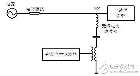
Active filtering and passive filtering are mixed in many occasions due to their respective advantages (low passive cost, high active cost, and good dynamic compensation).
GB: "Power quality voltage sag and short-term interruption" (GB/T30137-2013)
Voltage sag: Voltage sag or drop refers to the phenomenon that the effective value of the supply voltage suddenly drops and recovers in a short time. The duration of this phenomenon in the power grid is mostly 0.1 to 1.5 s.
The voltage dip is a two-dimensional electromagnetic disturbance, that is, the magnitude of the voltage drop (residual pressure or sag depth) and time.

The process of sag:
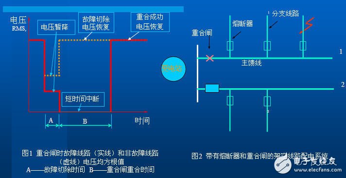
Multiple voltage events may occur in one fault. Take the diagram as an example to illustrate the development from a short-term interruption and a voltage sag to a second short-term interruption and a secondary voltage sag until a long-term power interruption.
The cause of the voltage sag phenomenon:
1) The most common cause of severe voltage sags is the failure of system components or lines. (The impact of severe weather such as lightning is mostly). Features: large sag, nearly rectangular curve, short duration (ie fault online time).
2) Another major cause of voltage sags is the start of heavy loads. Features: small sag, irregular rectangle, long duration.
Voltage sag three feature quantities: sag amplitude, duration and sag frequency are the three most important feature quantities of the nominal voltage sag severity.
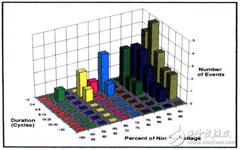
US EPRI-DPQ voltage sag statistical survey distribution results
â–² The voltage sag with a sag of 0.7pu-0.9pu is 70%. ;
â–² About 90% of the duration does not exceed 1s, and about 60% does not exceed 0.1s;
â–² The frequency of occurrence is lower than 0.7pu for 18.422 times/year, and below 0.9pu is 56.308 times/year.
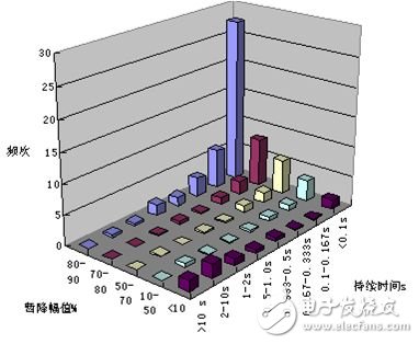
Control measures: 1) use voltage compensation type device; 2) install voltage loss trip device in main switch; 3) high voltage power supply safety protection wall.
It has been proved by practice that the effective treatment of voltage sag needs to be considered and separately treated from the power supply side and the power supply side. Strictly according to the power quality standard, the means of reducing or eliminating the voltage sag impact is adopted for different users and equipment characteristics. To achieve satisfactory dynamic power quality requirements.
ZGAR AZ CC Disposable
ZGAR electronic cigarette uses high-tech R&D, food grade disposable pod device and high-quality raw material. All package designs are Original IP. Our designer team is from Hong Kong. We have very high requirements for product quality, flavors taste and packaging design. The E-liquid is imported, materials are food grade, and assembly plant is medical-grade dust-free workshops.
Our products include disposable e-cigarettes, rechargeable e-cigarettes, rechargreable disposable vape pen, and various of flavors of cigarette cartridges. From 600puffs to 5000puffs, ZGAR bar Disposable offer high-tech R&D, E-cigarette improves battery capacity, We offer various of flavors and support customization. And printing designs can be customized. We have our own professional team and competitive quotations for any OEM or ODM works.
We supply OEM rechargeable disposable vape pen,OEM disposable electronic cigarette,ODM disposable vape pen,ODM disposable electronic cigarette,OEM/ODM vape pen e-cigarette,OEM/ODM atomizer device.


ZGAR AZ CC Vape,ZGAR AZ CC Vape disposable electronic cigarette,ZGAR AZ CC Vape vape pen atomizer , AZ CC E-cig,AZ CC disposable electronic cigarette
ZGAR INTERNATIONAL(HK)CO., LIMITED , https://www.szvape-pen.com
