
Overview:
The usual multi-string balanced charging scheme uses a 4.2V charging board and lithium battery one-to-one, and the structure is relatively complicated. Xiaobian inadvertently saw a single-supply lithium-ion multi-string balanced charging design designed by a power enthusiast. The scheme is simple but powerful. The most important one based on this scheme has attracted many other enthusiasts to actively discuss. Everyone has different opinions. There are also many other good ideas. Here is a small series to share and share.
Single-supply lithium-ion multi-string balanced charging design introduction:
The usual multi-string balanced charging scheme uses a 4.2V charging board and lithium battery one-to-one, and the structure is relatively complicated.
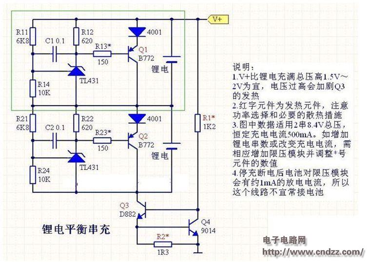
è¶There is a plan for the holiday, you can use only one ordinary DC power supply to balance the charging of multiple strings of lithium batteries. The lines are not complicated, all use conventional components, which is more suitable for self-made. The figure below shows the actual circuit diagram of 2 series of 500mA current. The green frame is a complete parallel voltage limiting module, and each of the two lithium batteries is used.
Single-supply lithium-ion multi-string balanced charging design
When the lithium battery voltage is lower than 4.2V, the B772 is turned off, and the charging current is all entered into the battery for constant current charging. When the lithium voltage rises to near 4.2V, 431 begins to conduct micro-conduction, and B772 turns on to shunt lithium battery, which is similar to the constant voltage charging phase of lithium battery. Until the charging is completed, 431 is turned on, and the module voltage is stable at 4.2V. At this time, the charging current is completely bypassed by B772, and the battery is not charged.
The bottom Q3/Q4 is a simple constant current source, which keeps the total current of the power supply circuit constant. If the charging current is not strict, a high-power current limiting resistor can be used instead of this constant current source.
If the charging power is large, in order to avoid the loss on the voltage limiting module after the battery is full, you can also consider adding a full power-off function. Fully automatic power-off lines are a bit more complicated, if only small and medium current applications, no added.
The most important thing to pay attention to on the entire line is the heat of the B772. When charging starts, it has no temperature. After the charging is completed, the charging current is bypassed by it, which will generate 3.5V*0.5A of dissipated power. Therefore, it is necessary to add an appropriate heat sink. When the supply voltage V+ is high, Q3 The heat will also increase, and if necessary, add a heat sink.
This is just a basic circuit, and if necessary, you can add a full indicator and a full stop. If you have good suggestions, please feel free to discuss! Welcome everyone to participate actively!
(Please read the PDF for details)
Flash Bracket,Light Stand Bracket,Camera Flash Mount,Camera Flash Holder
SHAOXING COLORBEE PLASTIC CO.,LTD , https://www.colorbeephoto.com