
Occasionally a circuit design requires dual power, but the only power supply available is a single power supply, usually a positive power supply. Many excellent dual-supply IC solutions are also available, but many project-appropriate solutions are available from idle devices. The simple circuit below produces dual supplies of about 9 volts and -4 volts, powered by a single 5 volt supply, with enough current to drive a simple op amp circuit. When the positive voltage supplies 3.5 mA (1k load), it drops to about 7 volts; when the negative voltage supplies 7 mA, it drops to about 3.5 volts. 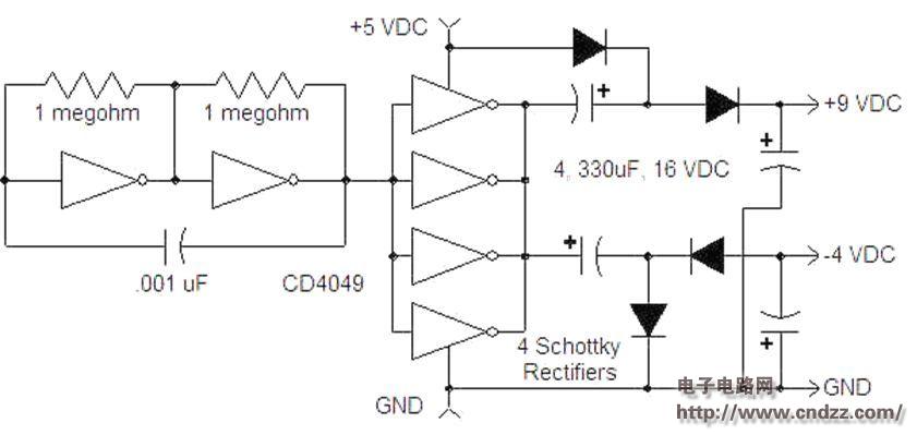
The circuit uses a CD4049 six-inverter. The two inverters on the left produce a square wave, and the other four inverters produce an output in parallel. When the output is low, the top capacitor is charged to approximately 4.5 volts. When the output is high, a voltage of 5 volts is connected in series with a voltage of 4.5 volts on the capacitor to obtain approximately 9.5 volts. The negative supply section also charges the capacitor and then produces a voltage of about -4 volts to ground without a voltage multiplication process.
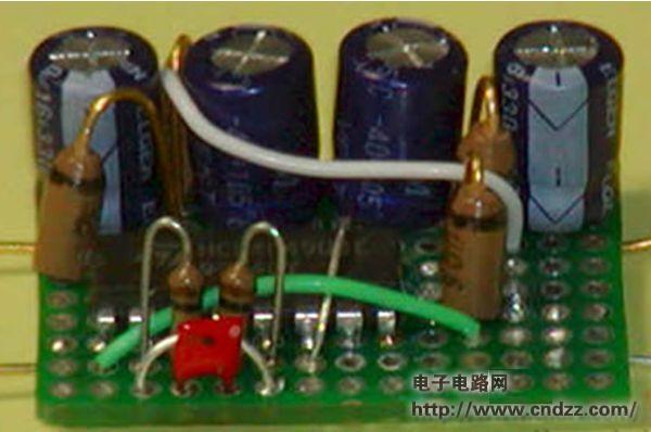
The prototype uses an old-fashioned é”— rectifier diode and the circuit operates at a frequency of only about 500 Hz. If you switch to a Schottky rectifier diode, you can set a higher operating frequency by lowering the .001 uF capacitor or by increasing the 1 megaohm resistor, say 5 kHz (try a 100k resistor or a 100pF capacitor). Such four 330 uF capacitors do not need to take such a large capacity, a few uF is enough.
Wall Power Switch,Smart Wall Switch,Double Wall Switch,Electrical Wall Switches
Wenzhou Niuniu Electric Co., Ltd. , https://www.anmuxisocket.com