
The use of high-power LEDs for lighting is a new topic in this century. The comprehensive advantages of energy saving, safety and long service life will lead to a new round of lighting revolution. In battery-powered LED flashlight applications, how do you extend battery life while using the same battery? This involves power management issues. This article introduces the design considerations of flashlight LED lighting circuits for several popular SP66?8EU driver circuits.
The luminous intensity of a 1W LED is determined by the current flowing through the LED diode. In order to maintain the luminous intensity of the LED, when the battery is discharged, the current flowing through the LED needs to be adjusted. When a voltage greater than VF is applied across the LED, current flows through the LED; VF refers to the forward voltage drop of the LED, and the forward voltage drop VF of the different LEDs is different, and as the ambient temperature changes Change; the typical VF of a 1W LED is 3.3V, which is higher than the voltage supplied by two No. 5 batteries. The voltage range of the two-cell battery is between 1.8V and 3.2V, so an additional boost circuit is required to boost the lower battery supply voltage to a higher output voltage.
This article refers to the address: http://
The booster circuit is as shown. When the switch in Figure 1 is turned on, the input voltage is applied across the inductor L1, causing the inductor L1 current to increase linearly. In the final phase of conduction, the inductor current increases to the peak value of Ipeak = Vin*Ton/L, at which point the switch is turned off. The energy stored in the inductor causes the voltage at node V1 to rise above Vin and until D1 is forward biased and turned on. At this point, the inductor current leaks through D1. During the switch-off period, the inductor current drops with a slope of (Vout–Vin)/L.
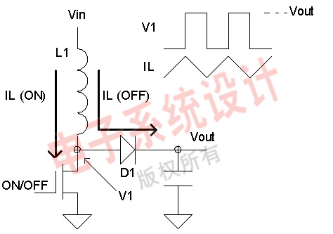
Figure 1: Simple boost block diagram.
In the steady state, there is no DC voltage across the inductor, otherwise a higher current will be generated. This also means that in a steady current, the volt-second value of the on state should be equal to the volt-second value of the off state.

or
In order to provide a high voltage output, the control loop needs to adjust the turn-on and turn-off times of the main switch. The switch is turned on and off by monitoring the change in output, so the current driving the LED needs to be adjusted. In order to achieve the above purpose, a small resistance (such as R3 in Fig. 2) is used to detect the current of the LED, and the voltage signal is output to the control loop.
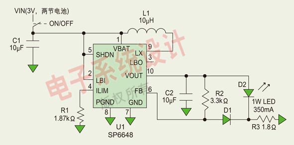
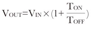
Figure 2: Control circuit for a two-fifth battery-powered 350mA LED.
In battery-powered currents, inverter efficiency is an important indicator of battery life. In order to improve efficiency, the rectifier diode D1 is replaced by an additional switch (synchronous rectifier), which is much less lossy than the diode, thus improving efficiency. This boost regulator function is implemented here with a special function integrated circuit that typically includes a main switch, a synchronous rectifier, and a precision reference and control loop.
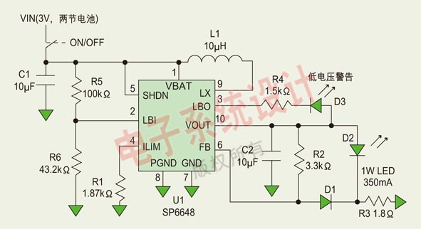
Figure 3: Control circuit with low voltage specifications for a two-cell, five-cell battery-driven 350 mA LED.
Figure 2 is a simple power regulator that converts two rechargeable five-cell batteries into the adjustable current required to drive a 1W LED. The voltage supplied by the two AA batteries is usually between 1.8V and 3.2V, so a boost is required to drive the LEDSP66?8. High-efficiency boost regulators allow the output current to be regulated at all voltages. With current feedback, the brightness of the LED is guaranteed to be constant even when the battery is discharged. The IC's synchronous rectification function ensures long battery life and high conversion efficiency. The current flowing through the LED is regulated by R3 of the following formula:
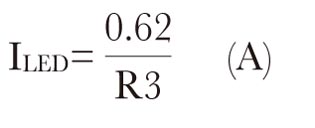
The resistance of R3 in Figure 2 sets the current through the LED to 350MA. It can be obtained from the above formula that increasing the resistance of R3 can reduce the current. Another way to control the brightness of the LED is to apply a DWN signal to the SHDN pin.
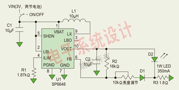
Figure 4: Two-section, five-cell battery-driven 350mA LED with control loop for brightness adjustment.
The SP66?8 always regulates the output current before the battery is discharged. As shown in Figure 3, in order to avoid the early occurrence of low-power warning, the detection circuit composed of SP66?8 is used to adjust the switch. When the LBI input voltage drops below 0.61V, the D3 switch gives a low voltage indication, which indicates that the voltage is too low. At this time, a current of about 1 mA flows through the LED. The value of the battery voltage drop can be detected by the following formula:

Substituting the values ​​of R5 and R6 in Fig. 3 into the above equation, the low voltage indicating value is about 2V.
There is only a slight difference between Figure 4 and Figure 2. Figure 4 includes an additional variable resistor with a full-scale of 10KΩ to adjust the brightness of the LED. When the current on the variable resistor approaches zero or exceeds 350 mA, the current on the LED does not change.
The complete solution offered by Sipex will miniaturize the entire circuit. In terms of cost performance, Sipex's LED driver is the best choice. For high current LED applications, the SP66?8 driver is the best choice. If you want to drive a larger current LED, you can choose Sipex's SP76?8, which can drive a 700mA LED. Sipex's boost drivers feature a simple design, small package size and good energy efficiency.
ZGAR AZ Mesh Vape Pods 1.0
ZGAR electronic cigarette uses high-tech R&D, food grade disposable pods and high-quality raw material. A new design of gradient our disposable vape is impressive.We equip with breathing lights in the vape pen and pods.
Our team has very high requirements for product quality, taste allocation and packaging design. Designers only use Hong Kong designers, e-cigarette liquid only imports from the United States, materials are food grade, and assembly factory wants medical grade without ground workshop.
We offer best price, high quality Mesh Pods,Pod System Vape,Pods Systems Touch Screen,Empty Pod System, Pod Vape System,Disposable Pod device,Vape Pods to all over the world.


Pod Systems Vape And Smoke,Vape Pod System Device,ZGAR AZ Mesh Vape Pods 1.0 Pod System Vape Kit,Pod System Mini Vape Pod
Zgar International (M) SDN BHD , https://www.szdisposable-vape.com