introduction
PID control system algorithm can not achieve static error-free control for medium and low frequency periodic signals; it also has poor ability to adjust the output waveform distortion caused by nonlinear load.
This paper introduces a scheme of PID controller and repeating controller adopting a series topology structure. The stable PID + control object closed-loop system is used as the control object of the repeating controller. The design of the controller.
1 Inverter model

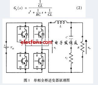
In the formula, u0 is the output voltage; i is the inductor current; is the load resistance; C is the filter capacitor; ï¿¡ is the capacitor's equivalent series resistance:

Taking the sampling frequency and the switching frequency to be equal, the inverter bridge is regarded as a zero-order holder, and the pulse transfer function of the object obtained by discretizing equation (2) is:
![]()
2 PID controller design
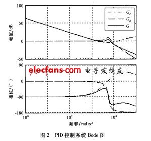
Figure 2 shows the open-loop frequency characteristic diagram (Bode diagram) of the PID control system. Among them, G0 is the controlled object; G is the PID controller; G = Gp & TImes; G0
According to the traditional PID design theory, the open-loop coefficient is first set to K = 200, the purpose is to increase the low-frequency gain of the system and reduce the steady-state error. However, excessive K value reduces the stability of the system, so a zero point is added at the low frequency band to form a lag correction with the integration link. There are two main functions of this hysteresis link: one is to increase the gain of the low-frequency response of the system and reduce the steady-state error of the system while ensuring that the transient performance of the system is basically unchanged; the other is to attenuate the system by using its low-pass filtering characteristics The high-frequency response gain improves the phase angle margin of the system to improve the stability of the system.

Add a zero at the mid-band 60, and add a pole at the high-band, which constitutes a lead correction. There are two main functions: one is to use the phase angle advance feature to increase the system's phase angle margin, increase the system's cut-off frequency, and ensure the system's fast dynamic response; the second is to attenuate the system's high-frequency response gain and suppress high-frequency noise, Improve system robustness.
G in Figure 2 is the open-loop transfer function of the PID control system. From its frequency characteristic curve, it can be seen that the low-frequency open-loop gain of the system is very large; the phase angle margin of the frequency band near the cut-off frequency increases; the high-frequency open-loop gain is very small and suppressed High-frequency interference signal. The PID controller is designed by lagging one leading phase correction method, and the expected purpose is achieved. After the above analysis, the PID transfer function is:

3 Repeat controller design
According to the internal model principle, the external periodic signal dynamic model is added to the closed-loop system, then the system can achieve the purpose of asymptotic tracking of the external periodic signal. The repetitive control strategy is based on this principle. Figure 3 is a basic repetitive controller system structure diagram, in which the discrete expression of the repetitive controller is:
![]()
In the formula, â…£ is the sampling frequency of the output voltage per fundamental cycle.
It can be seen from equation (6) that when the frequency is ∞ = 2 ~ k / T (K = 0, 1, 2, ..., T is the fundamental period), since z = 1, so if repeat control is embedded in the closed-loop system The converter will make the open-loop gain tend to infinity. In this case, the non-harmonic input signal will be strongly attenuated to achieve the purpose of accurately tracking the input signal. However, since the dynamic characteristics of the controlled object cannot be accurately known, the open-loop gain tends to infinity, which will deteriorate the stability of the closed-loop system. In order to ensure system stability, the basic repetitive control system needs to be improved.

The structure diagram of the compound repetitive control system proposed in this scheme is shown in Figure 4.

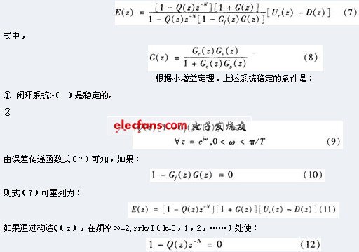
Q (z), G, (.) Are low-pass filter compensators and are the focus of repeating controller design work. The role of P () is to adjust the open-loop gain to a large finite value, and to ensure the stability of the system without affecting the steady-state accuracy; the role of G, () is to improve the system by limiting the frequency range of the repeating controller Robustness. The error transfer function of the system can be obtained from the graph:

Then E (z): 0 can be obtained. Therefore, when the system satisfies equations (10) and (12), the steady-state error of each harmonic will theoretically tend to zero. However, because the actual system is a non-ideal system, the above design requirements cannot meet the harmonics of all frequency bands, usually within a certain frequency range, according to the stability conditional formula (8), formula (9) and controller conditional formula (10 ), Equation (12) designs a repeating controller to meet the system's requirements for steady state and dynamics.
According to equations (8) and (10), the compensator G, () can be directly designed as the inverse function of G (). However, if G (z) is a non-minimum phase system, although equation (10) is still established, the external performance is stable. Due to the unstable zero-pole cancellation situation, this will lead to internal system instability. In this case, other types of compensators must be used to design G, ().
In the scheme proposed in this paper, the control object is a stable closed-loop system stabilized by a PID controller, which itself is the minimum phase system, so the inverse function can be used to design the compensator directly, namely:
![]()
Equation (12) theoretically requires p (z) = 1; however, equation (9) shows that since G (z) in the high frequency band tends to 0, Q (z) should be less than 1 in the high frequency band, so Q (z) should be a The expression of the low-pass filter with zero phase shift is:
![]()
In practical applications, the use of first-order low-pass filters can fully meet the system requirements:
![]()
Through the above analysis, the two filters of the repeating controller can now be designed according to equations (13) and (15).
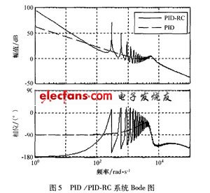
In order to further understand the role of the repetitive controller in the system, we can compare the open-loop frequency characteristics of the system with and without the embedded repetitive controller, as shown in Figure 5.

In the high frequency band, the open-loop gain becomes very small, which is very helpful to suppress high-frequency noise and improve system stability and robustness. However, at non-harmonic frequencies, the open-loop gain of the system without the embedded repetitive controller is larger, which indicates that the repetitive controller has a poorer control effect on the signal at this frequency. Therefore, in addition to the role of improving the system's dynamic response speed, the PID controller also has to adjust the non-harmonic signal to make up for the lack of repeated controllers.
At present, flat Zinc bar is the ideal material for the zinc static and dynamic balance block of vehicle wheel, with good corrosion resistance.
Excellent mechanical properties,elongation is up to 20% or more,the yield of balance pieces stamping is high.
Product specification: Ñ„19mm(width)*2.65mm(thick)
Product packing: 30-150kgs(special packaging specifications can be negotiated)
Flat Zinc Bar,Anode Zinc Bar,Galvanized Zinc Flat Bar,Zinc Coated Steel Flat Bar
Shaoxing Tianlong Tin Materials Co.,Ltd. , https://www.tianlongspray.com
