
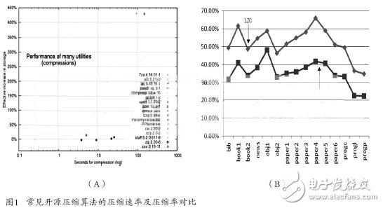
Through further research and comparison of various compression algorithms, this paper finds that the LZO compression algorithm is an algorithm called real-time lossless compression. The LZO compression algorithm provides a moderate compression ratio while ensuring the advantages of real-time compression rate. Figure 1 (A) shows the compression rate test results of the common open source compression algorithm under the Linux operating system. The LZO compression algorithm is extremely fast; Figure 1 (B) shows the compression ratio of the Gzip compression algorithm and the LZO compression algorithm. Test structure, as can be seen from the figure, the LZO compression algorithm can provide an average compression ratio of about 50%.
1 Basic principle analysis of LZO compression algorithm
1.1 LZO compression algorithm compression principle
The LZO compression algorithm uses (repetition length L, finger back distance D) to replace the string that has been present in the history string. The repetition length means that the string that appears later is the same part of the string that appears first. The length of the return distance refers to the distance between two identical strings (one byte per unit); if it has not appeared (defined as a new character), the number of new characters is output first. Then output new characters. For example, the string to be processed is “ABCDEFGHABCDEFJKLMâ€, the compression algorithm processes the characters one by one, and no duplicate characters are found when ABCDEFGH is processed; when it is processed to ABCDEF, it is found that these characters have appeared in the history string, and the calculation repetition length is 6, pointing back. The distance (current A distance from history A) is 8, then (6,8) is used instead of ABCDEF; no duplicate characters are found when processing to JKLM. After the string is processed, the entire string is compressed into: (08) h ABCDEFGH(6,8)(04)h JKLM, where h is hexadecimal.
1.2 LZO compression algorithm coding
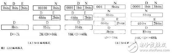
The LZO compressed data needs to be encoded in a specific format. As shown in Figure 2, the LZO compression algorithm has two purposes: to adjust the LZO compression ratio, so that the LZO is suitable for a short compression repeat length, but the return distance is long. Data; makes the decompression process much simpler, decompresses faster, and does not require additional memory.
2 LZO compression algorithm hardware design and acceleration scheme
2.1 LZO compression algorithm hardware structure
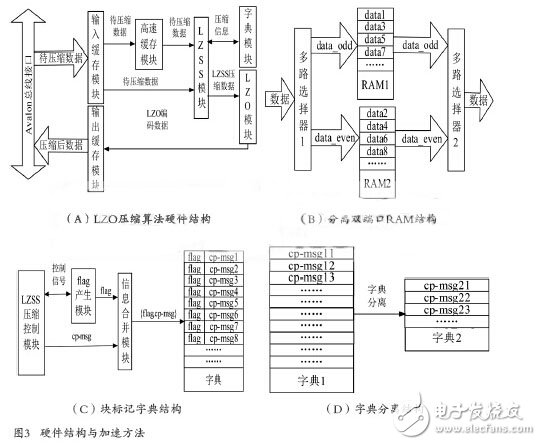
Figure 3 (A) shows the hardware structure of an LZO compression algorithm, in which the input buffer module is used to buffer the data to be compressed for DMA transmission, and provides a data source for the cache module to perform the compression operation; the cache module: Temporarily buffering data to be compressed, providing data to be compressed for the LZSS compression module, and writing a certain amount of data in advance during initialization; LZSS module: compressing the compressed data; dictionary module: storing compressed information generated during compression, such as historical characters The index information of the string, so that the historical string information can be provided for subsequent data compression; the LZO encoding module: encodes the LZSS compressed data according to the LZO encoding format, and packs the encoded data group into a fixed length data packet to facilitate the bus. Communication; output buffer module: cache coded data, provide compressed data source for DMA read operation; Avalon bus interface: package LZO compression algorithm module according to Avalon bus specification, provide preparation for subsequent integration of SOPC.
2.2 LZO compression algorithm hardware acceleration scheme
(1) Separate dual port RAM
In order to speed up the comparison process of the LZO compression algorithm string, this paper proposes the structure of the split dual port RAM as shown in Fig. 3(B). The multiplexer 1 in the figure is used to alternately write the data to be compressed into the dual port. In one of the RAM 1 and the dual port RAM 2, the multiplexer 2 is used to alternately output the read data. For example, the existing character ABCDEFGHIJ is to be stored in the dual port RAM, as follows: ABCD is written into data1 in RAM1 through multiplexer 1, and EFGH is written into data2 in RAM2 through multiplexer 1, IJ The data 3 is written by multiplex selection 1. At this time, the LZO compression algorithm module needs to read the string BCDE, and reads the B at the data2 in the RAM2 while reading the BCD at the data1 in the RAM1, that is, the address of the RAM1 is read. At the same time, the address can be read to RAM2, so that the contents corresponding to the two addresses can be read at the same time. Compared with the general dual port RAM structure, this structure can realize the read operation at one time. To further expand, the following conclusions can be drawn: If the width of the RAM is W, when the number of read characters is less than 2W, the read operation can be completed at one time by using the separate dual-port RAM structure; when the number of read characters is within 2~2W The general dual-port RAM structure may be read twice. Of course, not only the width of the RAM can be increased, but also the number of RAMs can be increased. When the width of the RAM and the number of RAMs are larger, the possibility of completing the read operation only once is greater.
(2) block mark
The LZO compression algorithm initializes the dictionary module to 0 before compressing each data block, that is, writes a 0 to the RAM, but a 0 write operation takes several cycles. If the dictionary module has a depth of 16K, that is, the depth of the RAM is 16K, it takes at least 16K cycles when the write 0 operation is performed. One way to solve such problems is usually to use a ping-pong operation, that is, to alternate between two dictionaries. In order to solve the problem of time cost and resource consumption caused by initialization, this paper proposes a block mark dictionary structure as shown in FIG. 3(C), which mainly includes: LZSS compression control module for generating compressed information, that is, characters. a hash value corresponding to the index and the character; a flag generating module, configured to generate 0 or 1 flag identifiers, indicating whether the current data block or the historical data block; and the information combining module, configured to merge the character index and the flag identifier, and then Save in the dictionary module. The working principle of the whole structure can be summarized as follows: flag identifier 0 or 1 indicates the current data block or historical data block, such as 0 when compressing the first data block, 1 when compressing the second data block, and compressing the third The data block is identified as 0, and the fourth data block is identified as 1 when it is compressed. The LZSS compression control module generates a character index and then merges with the flag to store the address corresponding to the hash value calculated by the character. For example, if it is assumed that the second data block has been compressed, according to the above working principle, the current identifier should be 1, and the information in the dictionary is taken out during compression and the first bit is determined. If the first bit is If it is 0, the compressed information is a historical data block, and the compressed information is invalid. If the first bit is 1, it may be the current data block (because it may be a long time ago), and the corresponding character is extracted according to the compressed information. Confirmation of the comparison.
In summary, the block mark dictionary structure has the following features: no initialization operation is required, and the time cost of the initialization process is avoided; the idea of ​​ping-pong operation is abandoned, and the consumption of a large amount of resources caused by the ping-pong operation is saved; the structure is on the chip. In the case of resource shortages, it is the best choice.
(3) Dictionary separation
In the process of implementing the LZO compression algorithm, when the collision occurs, the LZO compression algorithm performs a second hash operation, and the hash operation is offset based on the first hash operation. In order to improve the compression ratio of LZO compression algorithm, this paper proposes a dictionary separation structure as shown in Fig. 3(D). When a hash collision occurs, the LZO compression algorithm performs the second hash operation, but the second hash operation corresponds. The string index is no longer stored in the first dictionary, but a separate RAM space is created for storage. The total storage space of the dictionary separation structure increases the size of the dictionary 2, so that the amount of compressed information of the file is also increased during the process of compressing the file. It can be seen that this structure can improve the compression ratio of the LZO compression algorithm.
3 LZO compression system integration and test verification
3.1 LZO compression system hardware structure
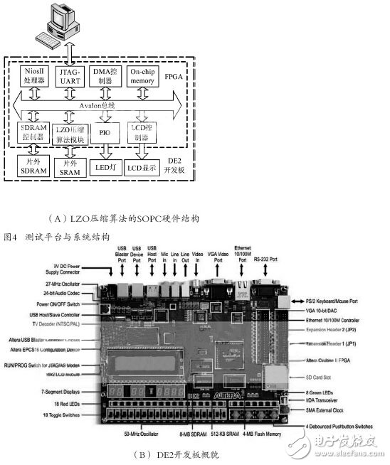
Figure 4 (A) shows the hardware structure of the LZO compression system SOPC. The inner layer dashed line indicates the FPGA. The module in the dotted line has the corresponding code or hardware circuit. The outer dotted line indicates the DE2 development board. The development board provides the corresponding resources. In the figure: the PC transmits the data to be compressed to the SDRAM on the DE2 development board through the download line. The data is compressed and then transmitted back to the PC via the download line; the Nios II processor is responsible for interacting with the user and managing the compressed data. Controls the normal operation of the entire SOPC; JTAG-UART is used for software and hardware debugging during the design process; DMA controller is used for high-speed data transmission, it transfers the data to be compressed in the off-chip SDRAM to the LZO compression algorithm module, and compresses LZO The compressed data in the algorithm module is transferred to the off-chip SDRAM; the LZO compression algorithm module is used to compress the data transmitted by the user, and communicates with the off-chip SRAM; the LCD controller is used to control the display of the LCD, and the LCD can display The LZO compressed file starts and ends, increasing the visibility of user interaction, such as displaying the size of the file to be compressed, the size of the compressed file, etc.; the PIO controls the LED indicator light on and off, and the LED light can be used to indicate the start of the LZO compressed file. End, increase the visibility of user interaction; On-chip memory is used to store software and hardware configuration information when the system starts; SDRAM controller is used to control SDRAM and system data SDRAM is used to store instructions and data; SRAM is used to store the compression information generated during the LZO compression algorithm, and plays the role of a dictionary in hardware design. The reason for using off-chip SRAM is that the on-chip resources of the FPGA may not be enough. All the above modules use the Avalon bus specification for data communication. They are commonly mounted on the data bus. The Avalon bus has its own arbitration structure, address analysis and other functions, which is easy for users to integrate and develop.
3.2 Development Board Introduction
The test and verification platform is shown in Figure 4(B). The core chip on the development board is Altera's Cyclone II EP2C35 FPGA. The development board was chosen as the test platform based on the following considerations: sufficient off-chip storage resources (SDRAM 8MB, SRAM 512KB); rich on-chip logic resources (35K LEs); rich peripherals for debugging (LCD) , 7-segment-displays); support Nios II embedded soft core; lower cost.
3.3 Test results and comparison
The board test is performed on the LZO compression algorithm module and the integrated system. On one hand, the functional correctness of the algorithm module and the integrated system is verified, and on the other hand, the performance of the algorithm module and the integrated system are tested. The test content includes: data compression rate (compressed file size / file size before compression), data compression rate (number of bytes processed in a single cycle).
As can be seen from Fig. 5(A), the maximum compression ratio is 1.pdf file, and the smallest one is the 7.mp3 file (the audio file has been compressed by the audio compression algorithm), and the average value is removed after removing the maximum and minimum values. The compression ratio is increased to 1.37%. It is not difficult to find through Figure 5(B) that the compression rate is the fastest 2.txt file, and the slowest is the 10.dll file. After removing the maximum and minimum values, the average is taken. Value, the compression rate is increased by 4.81 times.
Carbon Fiber Thermal Insulation Material
Carbon Fiber Thermal Insulation Material,Matched Carbon Fiber Tube,High Temperature Carbon Fiber Material,Graphene Composite Carbon Fiber Material
HuNan MTR New Material Technology Co.,Ltd , https://www.hnmtr.com