
I. Overview
1. Overview of the basic components
1.1 Mechanical structure
[Machine arm main structure]
The main body of the robot arm is hand-made. It consists of 15 parts and a total of 25 parts, including 3 different shafts, 5 bearings with 2 different specifications, 2 brackets, 1 bracket, 1 bearing. One piece of the first stage mechanical arm is 2 pieces, the second stage mechanical arm is a total of 2 pieces, the third stage mechanical arm is 1 piece total 2 pieces, and the mechanical arm connection parts are 3 pieces total 4 pieces, the shaft fixing part 2 A total of 4 pieces, and a total of 8 pieces of angle iron for fixing between the parts. Except for the bearing, the aluminum alloy parts are made of parallel aluminum alloy plates. The third-stage mechanical arms have two sides and are freely movable. They are composed of single aluminum alloy plates and one end is directly It is connected to the steering gear and the other end is fixed to the drum stick. The shaft is divided into a vertical shaft and a horizontal shaft, and the vertical shaft is sleeved with the stepping motor, and the horizontal shaft is respectively connected to the mechanical arms of the respective stages by the shaft fixing member and the bearing.
The overall appearance of a single-armed structure has a total of 5 degrees of freedom, of which 3 degrees of freedom are motor driven, wherein the stepper motor below the base is used for rotation and between the second and third stage robot arms The connected steering gear is used to drive the third-stage robot arm to rotate. Aluminum alloy plate parts are fixed by self-hardening angle iron to avoid sheet metal work on aluminum alloy parts to reduce cost and production time; shaft and aluminum alloy workpieces are mixed and fixed by means of shaft joints and bearings. Fit and fix. The whole mechanical arm uses a total of nearly 200g of screws and nuts, mainly used for the fastening of angle iron and aluminum alloy plates, and also uses a small number of fastening screws to fix the shaft and the fixed parts or the motor. The steering gear is also equipped with four fixing parts with perforations for holding the third stage robot arm. (See Figure 1.1 for details)
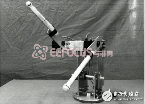
Figure 1.1 Physical diagram of the main structure of the robot arm
[base structure]
The base of the robot consists of two parallel plexiglass, of which two glass plates are connected by four studs. The panel is equipped with bearings and is screwed to the plexiglass floor through the small holes provided in the bearing. The bottom plate clamps the stepping motor through the angle iron, so that the stepping motor itself cannot rotate, the vertical shaft passes through the bearing and is connected with the stepping motor, the bottom of the vertical shaft is hollowed, and the motor shaft is nested in the vertical shaft, and Use a fastening screw to secure both. The panel also has 9 setscrews for supporting the drum. The space between the two backplanes is used to place the main control circuit board PIC, the stepper motor drive and one of the power supplies. (See Figures 1.2 and 1.3 for details)
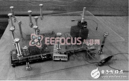
Figure 1.2 Schematic diagram of the internal part of the base part
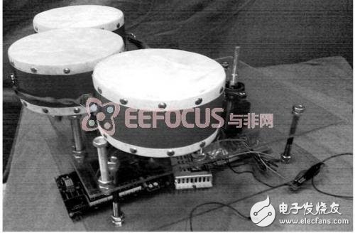
Figure 1.3 Overall physical picture of the base part
USB Power Sockets, USB Charger, USB Adaptor, Charging USB Ports, USB Quick Charger
NINGBO COWELL ELECTRONICS & TECHNOLOGY CO., LTD , https://www.cowellsockets.com