
The safety performance requirements of in-vehicle ECUs are very high. In terms of electrical, physical, and chemical aspects, major auto manufacturers usually have their own strict standards. Under normal circumstances, the external interface of the on-board ECU should have various fault protection circuits, the most important of which is the protection circuit when a short circuit occurs to the on-board 12V power supply or to the ground. Because the USB interface can directly output 5 volt power, short-circuit protection is particularly important. The protection circuit designed in this paper can effectively protect the USB power output line. No matter the USB power output line VBUS occurs a short circuit to 12V power or ground, it will not affect the normal operation of the internal circuit of the vehicle ECU, and achieves intrinsically safe short circuit protection. .
1 Introduction
In order to ensure driving safety, the safety performance of the on-board ECU is very high, and it is necessary to ensure that the failure rate is as low as possible during design. As the most widely used communication interface between mobile peripherals and the host, USB (Universal Serial Bus) has the characteristics of low cost, simple use, plug and play support, and easy expansion. It has been widely used in car entertainment and storage devices. application. Because the USB interface provides a built-in power supply, it can provide more than 500mA of current. For some devices with higher power, such as mobile hard disks, the instantaneous drive current can reach more than 1A. If the vehicle-mounted ECU has an interface that can directly output power, such as a USB bus, in order to prevent the interface circuit from damaging the body when the power supply or the ground is shorted, the interface part should usually have a protection circuit to perform fault self-diagnosis and protection Features. When the system has a fault, it can automatically record the fault code in the storage body and adopt protective measures to prevent system damage and avoid causing safety accidents.
2. Circuit design
Using a comparator and a peripheral circuit, this paper designs a protection circuit that can automatically detect whether the USB power output line has a short circuit to 12V power or ground, and can automatically cut off the power supply when a short circuit fault occurs. In addition, if it is detected that the connected device is not among the supported USB devices, the system can also use this circuit to actively disconnect the power supply and automatically control the power supply according to the connection status of the device. The specific circuit is shown in Figure 1.
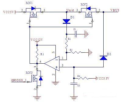
Figure 1 USB VBUS short circuit protection circuit
In the figure, MN1 and MN2 are two MOSFETs on the USB power channel, which are used to control the output of the 5 volt power supply, and their G terminals are connected to the output of the comparator. The potential value of the positive terminal of the comparator is jointly affected by 3.3 V and VBUS, and the potential value of the negative terminal is determined by Umid through the voltage division of the resistor. The value of Umid is always the same as the larger of VCC5V and VBUS. This book makes full use of the forward conduction and reverse cut-off of the diode, and utilizes the fast recovery diode in the MOS tube, and a window comparator can be formed by using a comparator. If the voltage on VBUS falls outside the window (for example, 12V power supply voltage or ground level), then the comparator outputs a low level, turning off the MOS tube of the power supply line. In this way, even if the 12V voltage cannot enter the system, it also prevents the system 5V power supply from overcurrent due to a short circuit to ground, which plays a role in protecting the system from short circuit interference.
3. Function demonstration
Assuming that the two input terminals of the comparator have potentials U + and U-, the output potential is UO, and the voltages of diodes D1 and D2 are UD1 and UD2, respectively.
U- = (Umid—UD1) R2 / (R2 + R3); (1)
Under normal working conditions, U- <U +, UO is high, and the MOS tube is in the open state. The following discussion will be divided into two cases according to the magnitude of the voltage value on VBUS. Analyzing how large the value is will invert the comparator output and turn off the power supply output.
a. If the VBUS voltage is greater than 5V, because of the reverse cut-off effect of diode D2, there are:
U + = 3.3V; (2)
And because of the role of fast recovery diodes in MN1 and MN2:
VBUS = Umid; (3)
When U-> U +, the output level of the comparator is inverted, that is:
(Umid—UD1) R2 / (R2 + R3)> 3.3 (4)
That is: Umid> 3.3 (R2 + R3) / R2 + UD1 (5)
Set the value of VBUS at this time as VBUSH, combined with formula (3), we can get:
VBUSH = 3.3 (R2 + R3) / R2 + UD1 (6)
That is, when VBUS is greater than 3.3 (R2 + R3) / R2 + UD1, the comparator will turn off the MOS tube.
b. If the VBUS voltage is less than 3.3V, there are:
U + = VBUS + UD2 (7)
Umid = VCC5V (8)
When U-> U +, the output level of the comparator is reversed. By formula (1), (4), (7), (8), set the value of VBUS at this time to VBUSL, there are
VBUSL = (VCC5V—UD1) R2 / (R2 + R3) —UD2; (9)
That is, when VBUS is less than (VCC5V—UD1) R2 / (R2 + R3) —UD2, the comparator will turn off the MOS tube.
Assuming that the output voltage compared is UO, its voltage transmission characteristics are shown in Figure 2:
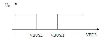
Figure 2 shows the voltage transmission characteristics from the above discussion. The circuit shown in Figure 1 can use only one comparator to form a window comparator with adjustable threshold, which achieves effective protection of the USB power supply circuit. When the voltage connected to VBUS is greater than VBUSH or less than VBUSL, the output of the comparator will become a low level, turn off the MOS transistors MN1 and MN2, and isolate the system power supply VCC5V and VBUS. The role of C1 and C2 in the circuit is to maintain the voltage of the comparator input terminal instantaneously. In addition, the circuit uses three power supplies with different amplitudes, of which VCC12V is used for the power supply of the comparator. The purpose is to short circuit the power supply when VBUS occurs. To prevent the input voltage of the negative terminal of the comparator from being greater than its supply voltage, but also to fully open the MOS transistors MN1 and MN2; VCC3.3V is used as the reference voltage of the positive terminal of the comparator. It is not recommended to set the reference voltage of the positive terminal higher than 3.3V , Because for some USB devices with large power consumption, the moment of connection will pull VBUS low. During this period, the value of VBUS will be between 3.3V and 5V. If the reference voltage of the positive terminal is greater than 3.3V at this time, there is a risk of the comparator malfunctioning.
For security reasons, when the system detects that the connected external device cannot be recognized, or belongs to an unsupported device, the system should turn off the USB power supply. At this time, the CPU can pull down the output of the comparator by turning on MN3, turning off MN1 and MN2. In this case, the power supply circuit of the peripheral device will act as a load in series with R4 and D2 to form a loop. Because the input resistance of the peripheral power supply circuit is very low, the non-inverting side of the comparator will be in a lower potential state, thereby generating a positive feedback effect, and prompting the comparator to output a low potential. Because the comparator and MN3 are both open collector / drain structures, with line and function, so the system CPU can turn off MN3 at this time, continue to maintain the low state of UO through the comparator. Only after the external device is disconnected, the input potential of the positive terminal of the comparator becomes high, and the power supply line of VBUS will return to normal.
The function of the above circuit has been verified in practical applications. With this circuit, when VBUS is short-circuited with 12V power supply or ground, the 5V power supply in the system is not affected at all, that is, the phenomenon of voltage recharging will not occur nor will it be pulled down to cause the system to reset.
Optical Rotary Sensor,Custom Encoder,Optical Encoder 6Mm Shaft,Handwheel Pulse Generator
Jilin Lander Intelligent Technology Co., Ltd , https://www.jilinlandermotor.com