
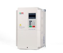
This article is mainly about the relevant introduction of the sd5000 inverter, and focuses on the detailed description of the sd5000 inverter fault code and the troubleshooting of the inverter.
Frequency converterA frequency converter (Variable-frequency Drive, VFD) is a power control device that uses frequency conversion technology and microelectronics technology to control an AC motor by changing the frequency of the motor's working power supply. The frequency converter is mainly composed of rectifier (AC to DC), filtering, inverter (DC to AC), braking unit, drive unit, detection unit and micro-processing unit. The inverter adjusts the voltage and frequency of the output power supply by breaking the internal IGBT, and provides the required power supply voltage according to the actual needs of the motor, thereby achieving the purpose of energy saving and speed regulation. In addition, the inverter has many protection functions. , Such as overcurrent, overvoltage, overload protection and so on. With the continuous improvement of industrial automation, frequency converters have also been widely used.
working principle
Overview
The main circuit is the power conversion part that provides voltage and frequency regulation power to the asynchronous motor. The main circuit of the frequency converter can be roughly divided into two categories
Frequency conversion power analyzer
The voltage type is a frequency converter that converts the DC of the voltage source into AC, and the filtering of the DC loop is a capacitor. The current type is a frequency converter that converts the DC of the current source into AC, and its DC loop filter is an inductance. It consists of three parts, a "rectifier" that converts industrial frequency power into DC power, and a "flat wave loop" that absorbs the voltage ripples generated in the converter and inverter.
Rectifier
A large number of diode converters are used, which convert the industrial frequency power supply into a DC power supply. Two groups of transistor converters can also be used to form a reversible current converter. Because of its reversible power direction, regenerative operation can be carried out.
Smooth loop
The DC voltage rectified by the rectifier contains a pulsating voltage of 6 times the frequency of the power supply. In addition, the pulsating current generated by the inverter also changes the DC voltage. In order to suppress voltage fluctuations, inductors and capacitors are used to absorb the pulsating voltage (current). If the capacity of the device is small, if the power supply and the main circuit components have a margin, the inductor can be omitted and a simple smoothing loop can be used.
Inverter
Contrary to the rectifier, the inverter converts the DC power into the AC power of the required frequency. A 3-phase AC output can be obtained by turning on and off the 6 switching devices within a determined time. Take the voltage-type pwm inverter as an example to show the switching time and voltage waveform.
The control circuit is a circuit that provides control signals to the main circuit of the asynchronous motor (voltage and frequency can be adjusted). It has the frequency and voltage "calculation circuit", the main circuit "voltage and current detection circuit", and the motor's "speed detection" "Circuit", the "drive circuit" that amplifies the control signal of the arithmetic circuit, and the "protection circuit" of the inverter and the motor.
(1) Calculation circuit: compare the external speed, torque and other commands with the current and voltage signals of the detection circuit to determine the output voltage and frequency of the inverter.
(2) Voltage and current detection circuit: It is isolated from the main circuit to detect voltage and current.
(3) Drive circuit: the circuit that drives the main circuit device. It is isolated from the control circuit so that the main circuit device is turned on and off.
(4) Speed ​​detection circuit: take the signal of the speed detector (tg, plg, etc.) installed on the asynchronous motor shaft machine as the speed signal, and send it to the calculation loop, and the motor can run at the command speed according to the command and calculation.
(5) Protection circuit: detect the voltage, current, etc. of the main circuit, in order to prevent damage to the inverter and asynchronous motor when an abnormality such as overload or overvoltage occurs
Important steps before the inverter is energized
Determine whether the main circuit is damaged. Use a multimeter diode file, connect the black pen to "+", and the red pen to R, S, T, U, V, W respectively. If the values ​​are all about 0.3-0.5V, it means that the upper bridge of the rectifier and inverter is good; On the contrary, connect the red pen to "-" and the black pen to R, S, T, U, V, W respectively. If the value is about 0.3-0.5V, it means that the lower bridge of rectifier and inverter is also good. If the measured values ​​are very different or severely unbalanced, it means that a certain phase of the module has been damaged. In this case, do not power on. After the main circuit is judged to be normal, the power-on inspection can be carried out in general. Because the internal circuit of the inverter itself is more complicated and there are many protection circuits, in some cases these circuits are prone to failures and the inverter reports related faults.
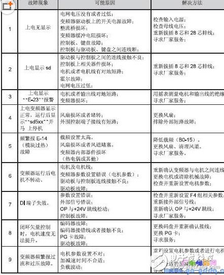
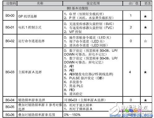
The following takes INVT inverters as a column to explain the common fault codes of INVT inverters in detail:
1. Inverter unit failure (OUT)
This fault includes OUT1, OUT2, and OUT3, which respectively represent U-phase, V-phase, and W-phase faults of the inverter unit. This fault generally only occurs in machines that drive optocouplers using PC929, which means that the drive boards include 1270 series, 1290AV03, 1250AVS series, 1258AVS series, etc.
[Overhaul ideas] OUT faults are generally divided into power-on jump OUT; running jump OUT; load load jump OUT. This reason is generally because the detection circuit detects the abnormal voltage of the inverter tube VCE and outputs an alarm signal. When the control board detects this signal, it immediately stops the drive output and displays the fault code. Of course, false protection caused by the abnormality of the protection circuit itself cannot be ruled out. It is worth noting that in some cases, the unstable output of the switching power supply will affect the power supply of the drive circuit and cause the machine to jump OUT irregularly. If the starting current of the cooling fan is too large, it will jump OUT every time the fan starts. Pay attention to the distinction during maintenance.
(1) For power-on OUT fault: This problem is generally due to the protection circuit itself or the driver part, and the module gate has obvious short-circuit or open circuit conditions. It can be judged by shielding the corresponding phase OUT protection signal. If everything else is normal after shielding, it means that the problem is caused by the bad protection circuit itself. Run after shielding. If there is a three-phase unbalance, it means that there is a problem with the drive circuit or the module.
(2) For the running OUT fault: this problem is generally caused by the drive circuit and the module itself. First, you can use a multimeter to test the relevant parts of the drive circuit and the module gate for obvious short-circuit and open-circuit phenomena. Shield the operation of the OUT protection signal of the relevant phase, and test whether the drive waveform is normal (when there is no oscilloscope, you can use a multimeter to compare and test the drive waveforms of each channel). Focus on the shape, amplitude, and dead time of the waveform, and finally check whether the IGBT is damaged. Compare other phases to test whether the drive gate junction capacitance is normal (multimeter capacitance file).
(3) For the OUT fault of the on-load load: This situation is slightly more difficult to repair than the first two. First, check whether the protection circuit itself has poor component performance. Under the premise of correct detection, replace the suspected diodes and chip capacitors with replacement methods (note that the OUT signal detection circuit on the control board is normal, and the replacement method can be used). Second, compare and detect whether the drive circuit drives the optocoupler to supply power normally, and whether the gate drive resistance changes. Third, do not load to test whether the driving waveform is normal. Finally, carefully judge and test whether there is a problem with the IGBT itself.
2. Current detection failure (ITE)
This fault is relatively simple, and is generally caused by a fault in the current detection circuit. At present, the current detection circuit mainly used by the company has two forms: Hall sensor detection and 7840 optocoupler isolation detection.
(1) Hall sensor detection: For the current detection circuit using the Hall sensor power-on trip ITE fault, only need to test the key point voltage to determine the fault location.
[Hall judgment] When the Hall ±15V power supply is normal, the static (unloaded) voltage of the signal output pin of the Hall should be zero. If it is abnormal, it means that the Hall is damaged.
[Op-amp circuit detection] The current op-amp IC model used by the company is TL082, which contains two independent operational amplifiers inside, pin 1 and pin 7 are output pins, pin 4 and pin 8 are ±15V power supply pins, 2, 3 , 5 and 6 pins are signal input pins. Under normal circumstances, the static (without load) voltage of the TL082 output pin is zero.
(2) 7840 optocoupler isolation detection: the latter stage of 7840 optocoupler isolation detection also uses TL082, and the detection method is the same as before.
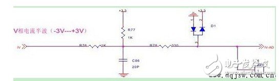
[Detection of Optocoupler 7840] The hot and cold ends of the 7840 optocoupler each have a set of 5V power supply. In actual maintenance, it is found that the 5V power supply of the hot end is more prone to failure and cause ITE. The 5V power supply is added to pins 1, 4 of the 7840 after being stabilized by the 78L05 by the driving power supply of the corresponding phase. Among them, the 2 and 3 pins of the 7840 are the detection signal input pins. Pins 5 and 8 are the cold end 5V power supply pins (the 5V of the control board is the same power supply). Pins 6, 7 are signal output pins, and the static voltage (without load) is 2.5V. If the voltage output of pins 5 and 6 is detected to be unbalanced, it is generally because the 5V power supply of the hot end is abnormal or the 7840 itself is damaged. It is worth noting that: 7840 hot and cold end 5V power supply non-switching power supply switching transformer is provided by the same winding, so pay attention to the correct selection of the grounding point when detecting the voltage.
The following figure shows the U-phase current detection circuit of the 1240AV08 driver board. The V and W phases are the same.
3. POFF failure
Generally, there are only three reasons for displaying POFF failure: (1) The DC bus voltage detected by the machine is seriously low. (2) The lack of phase signal is abnormal. (3) The 220V machine voltage level parameter is set incorrectly.
[Judgment method] Use the shift key on the keyboard or the mask to switch the display to the state of displaying bus voltage. Compare the displayed value with the measured value. If the deviation is large, it means that the busbar detection circuit is abnormal. Conversely, if the deviation of the two values ​​is very small or equal, it means that the phase loss signal is abnormal. At present, there are two types of bus detection circuits used by our company: resistance voltage divider and operational comparison amplification (TL082). The corresponding relationship is that the 0-3.3V output by the detection circuit corresponds to the 0-1000V of the actual bus. The two circuits are relatively simple, and the fault point can be easily found by testing the voltage at the key points in the circuit during maintenance.
When detecting the lack of phase circuit, directly test the lack of phase board and whether the PL signal on the drive board is normal. Normally, PL is low level, when phase is missing, it is square wave, and when power is off, it is high level. Note: The PL signal output by the drive board or the lack of phase board is sent to the CPU after level switching on the main control board. Please pay attention to determine whether the fault is caused by the main control board or the lack of phase board during maintenance.
ConclusionThis is the end of the relevant introduction about the sd5000 inverter. If there are any deficiencies, please correct me.
Related reading recommendation: Inverter inverter circuit schematic diagram Related reading recommendation: This article takes you to quickly understand the inverterSpring Clamp Terminal Block,Spring Terminal Connector,Spring Loaded Terminal Blocks,Spring Cage Terminal Block
Cixi Xinke Electronic Technology Co., Ltd. , https://www.cxxinke.com