
There are two main types of DC regulated power supplies used in modern electronic equipment: linear regulated power supplies and switching regulated power supplies. The so-called linear regulated power supply has the advantages of good stability, small output voltage ripple, and reliable use, but it usually requires a large and bulky power frequency transformer and a filter with a large volume and weight. Since the adjustment tube works in a linear amplification state, in order to ensure the output voltage is stable, the collector and the emitter must withstand a large voltage difference, resulting in a large power consumption of the adjustment tube, and the power supply efficiency is very low, generally only about 45%. . In addition, since the adjustment tube consumes a large amount of power, it is necessary to use a high-power adjustment tube and a large-sized heat sink, which is difficult to meet the needs of the development of modern electronic equipment. Switching power supply has advantages in efficiency, volume and weight compared with linear power supply. Especially with the continuous development and maturity of pulse width modulation technology and resonant conversion technology, high frequency switching power supply is becoming lighter, smaller and more efficient. High and reliable, this makes high frequency switching power supplies the most widely used power supply.
Switching power supply design always takes overall considerations first, then design each part of the power supply separately, followed by design overall and auxiliary functions, and finally test and design optimization.
The switching power supply is composed of an input rectification and filtering circuit, a high frequency transformer circuit, a rectifying freewheeling and filtering circuit, a protection circuit, a feedback circuit, a control circuit and a power switch. The input rectification filter circuit is used to filter the clutter in the power grid, and is also the DC voltage required to obtain the output through rectification. The high-frequency transformer is one of the key components of the switching power supply design. It functions as electrical isolation, voltage transformation, energy storage, variable current or variable resistance in the circuit loop. The output rectification freewheeling and filtering circuit obtains the DC current required for the output through the rectifying freewheeling function, and of course filters the excess clutter through the filter. The feedback circuit can be voltage feedback or current feedback. It compares the current and voltage values ​​sampled by the output with the controller's reference current and voltage values ​​to provide feedback. The controller adjusts the output of the current and voltage of the circuit through the information of the feedback circuit, and the output current reaches a stable value as much as possible. The power switch tube is controlled by the controller PWM to control its on-time, and the pulse width is adjusted to achieve the duty cycle adjustment.
The relationship between constant current and constant pressure is very close, and the two complement each other and can transform each other. The differential response of the constant current source and the constant voltage source on the circuit is different in the objects collected by the sampling circuits of the two. In order to keep the output voltage constant, the constant voltage source needs to track and control the output voltage in real time. The output voltage does not change with the load change under the condition of load change, and the constant current source refers to the controller under the condition of load change. The output voltage can be adjusted according to the change of the load. Keeping the output current constant, the constant current source sampling circuit collects the output current signal, but actually collects the voltage signal of the reaction current after I/V conversion.
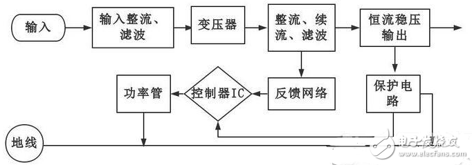
1. The AC power input is rectified and filtered into DC;
2. Control the switching tube through the high-frequency PWM signal, and add that DC to the primary of the switching transformer;
3. The secondary of the switching transformer induces a high-frequency voltage, which is supplied to the load through rectification and filtering;
4. The output part is fed back to the control circuit through the current sampling circuit, and the current change can be converted into a voltage change by the sampling resistor RS, and the duty ratio is adjusted by the PWM control chip to adjust the output voltage thereof, thereby achieving the purpose of constant current. RS can use constantan wire. Since the current sampling resistor is in the drive loop to prevent malfunction caused by noise, an appropriate RC filter can be used at the current signal input.
Bulk usb drives for sale,Bulk USB Drives - Premium USB,custom USB drives,Amazon flash drive,USB memory direct,Promotional USB drives
Shenzhen Konchang Electronic Technology Co.,Ltd , https://www.konchangs.com