
Urban traffic congestion is becoming more and more serious. How to optimize traffic signal control and improve vehicle traffic efficiency is an urgent problem to be solved. However, the existing traffic signal control system uses almost all fixed-time control methods, and cannot adaptively adjust the release time of each lane for actual traffic flow, resulting in waste of road resources.
In this paper, an adaptive traffic light control system based on wireless sensor network is designed. The sensor nodes carrying the ultrasonic transceiver module installed in each lane are used to detect the traffic flow. The traffic information is gathered into the centralized controller through wireless communication. The centralized controller runs the scheduling algorithm, and adaptively sets the traffic time of the corresponding lane vehicle according to the traffic flow, thereby improving the road utilization efficiency. In this system, the wireless communication mode is adopted between the centralized controller and the sensor node, and the communication cable does not need to be laid, and the installation is very convenient. The wireless sensor nodes densely distributed on the road can accurately sense the number of vehicles and the size of each lane, and provide accurate traffic information for adaptive signal control.
2, system designAs shown in Figure 1, the system consists of the following components: 1) centralized controller; 2) wireless sensor node; 3) signal light. The system can transmit the vehicle flow information and the signal working state to the remote monitoring computer through the metropolitan area network, or receive the remote monitoring computer control command.
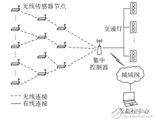
Figure 1 System composition
The centralized controller is the core device of the system and has the following functions: 1) Communication with wireless sensor nodes. In this system, the centralized controller functions as a sink node in the wireless sensor network, and the data collected by each node is finally gathered here. Therefore, the centralized controller must be equipped with a wireless transceiver module that matches each node. 2) running scheduling algorithm; 3) signal light control; 4) communicating with remote monitoring computer. It can be seen that the system has high requirements for centralized control performance, so it adopts ARM processor design.
Wireless sensor nodes are the key devices for detecting traffic flow information. Each sensor node can carry multiple sets of ultrasonic transceivers for detecting the vehicle. Nodes can be powered either by cable or battery. The cable power supply method has a large construction amount, and the battery operation power has a higher operation and maintenance cost.
This system has no special requirements for the function of the signal light. Generally, a set of signal lights is set in the direction of traffic of each vehicle at the traffic intersection.
Due to the large number of sensor nodes in the system, wireless communication between the centralized controller and the node greatly reduces the construction difficulty. A wired connection is used between the centralized controller and the signal lamp, so that when the communication between the sensor node and the controller is interfered by the radio, the centralized controller can abandon the adaptive scheduling and change the predetermined timing control signal lamp to avoid causing the whole System 瘫痪.
3, hardware design 3.1, wireless sensor node designThe wireless sensor node used in this system consists of three parts: the processor board (including RF circuit and power supply), the backplane and the sensor board. A processor board can be connected to multiple sensor boards with a cable connection between them. Its hardware block diagram is shown in Figure 2.
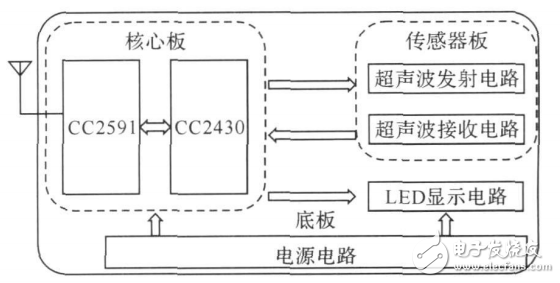
Figure 2 Wireless sensor node hardware block diagram
3.1.1, processor board designThe processor board is designed with CC2430 as the core. The CC2430 is actually a circuit that integrates CC2420 RF chip and C8051 MCU on one chip. It has its own wireless transceiver, FLASH, RAM, 14-bit ADC, timer, AES128 coprocessor. Resources such as watchdogs, hardware support CSMA/CA, support for a variety of power management modes, low power consumption, high wireless receiving sensitivity, strong anti-interference ability.
The processor board is shown in Figure 3. Due to the insufficient transmission power inherent in the CC2430, we have added an RF power amplifier circuit. The power amplifier chip is CC2591, the measured transmit power is 18dBm, and the communication distance is up to 500m. Some of the pins of the CC2430 are configured as outputs that are amplified by the driver and connected to the input of the sensor board. The other part is configured as an input that is connected to the output of the sensor.
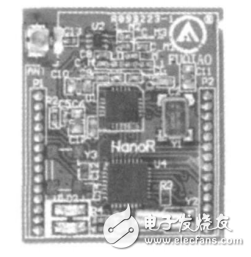
Figure 3 processor board
3.1.2, ultrasonic sensor board designThe sensor board is composed of four parts: an ultrasonic transmitter, a receiver, a transmitting circuit, and a receiving circuit. The ultrasonic transmitter uses a piezoelectric ceramic sensor T: 40:12, and the receiver uses a paired R: 40:12. The transmitting circuit adopts the audio set to successfully put the chip LM386, which has the advantages of low power consumption, wide working voltage range and adjustable gain (20~200 times). The excitation signal of the transmitting circuit is a 40 kHz square wave pulse with a duty ratio of 50%, which is provided by the processor board. After being amplified by the transmitting circuit, the piezoelectric ceramic sensor T: 40:12 is driven to generate ultrasonic waves. The receiving circuit adopts the infrared detecting receiver CX20106 which is often used in the remote controller of the television. The center frequency of the band pass filter is adjustable from 30 to 60 kHz, so it can also be used as an ultrasonic detecting circuit. Its internal circuit is shown in Figure 4.
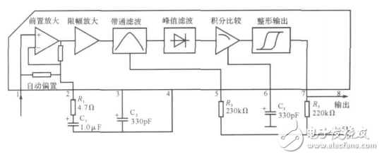
Figure 4 ultrasonic detection circuit
Washing Machine Motor,Spin Motor Of Aluminium Wire,Washing Machine Motor Shaft,Automatic Washing Machine Spin Motor
WUJIANG JINLONG ELECTRIC APPLIANCE CO., LTD , https://www.jinlongmotor.com