
Currently, for engineers, EMI (electromagnetic interference) and EMC (electromagnetic compatibility) are not too difficult tasks, even if they are not a disaster. This is because finding the source of annoying EMI radiation that is slightly beyond the limits can be cumbersome without the proper tools. This EMI radiation can span RF signals, analog signals, and digital signals.
Current designs are becoming more powerful, more complex, and smaller. More and more functions are being stuffed into smaller and smaller packages. Even if there is no wireless function, there are still a large number of components in the design. Each component will emit some kind of electromagnetic energy (or RF noise), which may interfere. Something else in the design. For this reason, the industry has established EMC rules and regulations that specify how much electromagnetic energy is allowed to propagate for any given design and which electromagnetic energy is allowed to propagate. But before meeting these goals, designers must confirm that their design "has no problem in itself."
Below is a general block diagram of a tablet or smartphone that includes all major components and multiple wireless transmitters. Each component must meet specific EMI standards so as not to interfere with other components, and the entire system must meet local regulations.
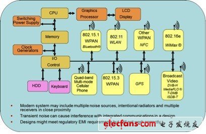
Modern system may include mulTIple noise sources, intenTIonal radiators and mulTIple receivers in close proximity: modern systems may include multiple adjacent noise sources, intentional radiation devices, and multiple receivers
Transient noise can cause interference with integrated communicaTIons in a design: Transient noise can cause interference in integrated communications in the design
Designs might regulatory EMI requirements but still not work correctly: The design may meet EMI requirements but still does not work properly
EMI and EMC have become major issues for designers and their companies because they will not be able to sell products if they do not meet regulatory requirements. In addition, EMI testing for certification requirements can be complex and costly. Before going for certification, designers must ensure that the design passes the test with great possibilities.
Therefore, we have to debug the design cycle, and we need to determine how to use MDO (Mixed Domain Oscilloscope) to make this debugging easier and clearer.
For security reasons, you need to analyze every potential EMI problem. This means that when determining RF signals that can cause EMI problems, it is necessary to trace back the source. Triggering events in multiple domains and realizing the time correlation of analog, digital, and RF signals in multiple domains plays a key role in this debugging process.
When a potential problem is discovered, such as an RF burst, the MDO can trigger the burst and then browse the rest of the system to find its source. Once you find the true source of this particular burst, you can use the appropriate device to determine the best way to reduce the burst. Can it be completely ignored? Can you suppress the effects of bursts by adjusting the timing of the source or different signals in the design? Or is it not necessary to shield the RF burst to prevent other components from being affected or meeting EMI specifications?
EMI is a complex problem that requires full testing in both the time and frequency domains and testing the interaction and interoperability of different signals in the design. MDO has a unique ability to correlate causes and results across multiple domains, marking a fundamental change in test equipment and opening up new, and certainly easier, ways to debug EMI issues.
Classroom Capture Media Processor
Classroom Capture Media Processor,Touch Control Panel,Classroom Recording Processor,Intelligent Recording Processor
SZ REACH TECH,.CO LTD , https://www.szreachtech.com