
A differential signal uses a value to represent the difference between two physical quantities. Strictly speaking, all voltage signals are differential because one voltage can only be relative to the other. In some systems, the system 'ground' is used as a voltage reference point. When 'ground' is used as a voltage measurement reference, this signal planning is called single-ended. We use this term because the signal is represented by the voltage on a single conductor.
On the other hand, a differential signal acts on the two conductors. The signal value is the voltage difference between the two conductors. Although not necessary, the average of these two voltages will always be consistent.
We use a method to compare differential signals. The differential signal is like two people on the seesaw. When one person is picked up, the other person is knocked down - but their average position is constant. To continue the analogy of the seesaw, a positive value can indicate that the person on the left is higher than the person on the right, while a negative value indicates that the person on the right is higher than the person on the left. 0 means that both people are at the same level.
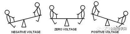
Figure 1 Differential signal represented by a seesaw
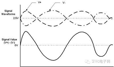
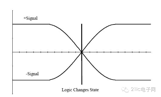
Applied to the electrical, the two jaws are represented by a pair of wires identified as V+ and V-. When V+>V-, the signal is defined as the positive signal, when V+ Figure 2 Differential signal waveform and single-ended equivalent Figure 2 The average voltage of the differential pair around the swing is set to 2.5V. When each signal of the pair is limited to an amplitude of 0-5V, offsetting the differential pair provides a maximum range of signal swings. This is often the case when operating with a single 5V supply. When a differential signaling scheme is used without a single-ended signal, we replace the single conductor with a pair of wires, adding complexity to any associated interface circuitry. So what kind of tangible benefits does differential signaling provide to prove that complexity and cost increases are worthwhile? The first benefit of the differential signal is that because you are controlling the 'reference' voltage, you can easily identify small signals. In a ground-based, single-ended signaling scheme, the exact value of the measured signal depends on the consistency of the 'ground' within the system. The further the source and signal receiver are, the more likely they are to differ between the local voltage values. The value of the signal recovered from the differential signal is largely independent of the exact value of 'ground', but within a certain range. The second major benefit of the differential signal is that it is highly immune to external electromagnetic interference (EMI). An interference source affects each end of the differential signal pair to the same extent. Since the voltage difference determines the signal value, this will ignore any similar interference that occurs on both conductors. In addition to being less sensitive to interference, differential signals generate less EMI than single-ended signals. A third benefit of differential signaling is the ability to accurately handle 'bipolar' signals in a single-supply system. In order to handle the single-ended, single-supply system bipolar signal, we must establish a virtual ground at any arbitrary voltage (usually the midpoint) between the ground and the mains. The positive signal is represented by a voltage higher than the virtual ground, and the negative signal is represented by a voltage lower than the virtual ground. Next, the virtual ground must be correctly distributed throughout the system. For differential signals, such a virtual ground is not required, which allows us to process and propagate bipolar signals with a high fidelity without relying on the stability of the virtual ground. Just mentioned single-ended signals, in fact, signals are usually propagated along the circuit in three modes: single-ended, differential, or common-mode. Single mode is the one we are most familiar with. It consists of a single wire or trace between the driver and the receiver, and the signal travels along the trace and returns from the ground. The most difficult to understand here is the common mode signal. It can include either single-ended traces or two (and possibly more) differential traces. The same signal flows along the trace and the return path (ground) or along two traces in the differential pair. Most people are often unfamiliar with common-mode signals because we never deliberately produce them ourselves. They are usually caused by noise coupled into the circuit from other (adjacent or external) sources. In general, the best results are neutral and the worst is destructive. Common-mode signals can generate noise that interferes with the proper operation of the circuit and are a source of common EMI problems. Differential signals have a significant disadvantage over single-ended signals: they require two traces instead of one, or twice the board area. However, differential signals have several advantages: if there is no return signal through the ground, the continuity of the ground loop becomes relatively unimportant. Therefore, if we have an analog signal connected to the digital device through a differential pair, there is no need to worry about crossing the power supply boundary, the plane is discontinuous, and so on. Power splitting of differential devices is also easier to handle2. Differential circuits are very beneficial in low voltage signal applications. If the signal level is very low, or if the signal-to-noise ratio is a problem, the differential signal can effectively multiply the signal level (+v-(-v)=2v). Differential signals and differential amplifiers are typically used in the input stage of systems with very low signal levels. Differential receivers tend to be sensitive to differences in input signal levels, but are often designed to be insensitive to the common mode offset of the input. Therefore, in strong noise environments, differential signals tend to perform better than single-ended signals. Compared to single-ended signals (referred to as a less accurate signal that is disturbed by noise at other locations on the board), the flip timing of the differential signals (referenced to each other) can be set more accurately. The intersection of differential pairs is defined very accurately (see Figure 3). The intersection of a single-ended signal between logic 1 and logic 0 is subject to, for example, noise, noise thresholds, threshold detection problems, and the like. Figure 3 Logic level changes state at the exact position of the differential signal intersection Mining is the process of creating a block of transactions to be added to the Ethereum blockchain in Ethereum's now-deprecated proof-of-work architecture.
Mining is the lifeblood of any proof-of-work blockchain. Ethereum miners - computers running software - used their time and computation power to process transactions and produce blocks prior to the transition to proof-of-stake.
ETH Miner:Antminer E9 2.4Gh/S,Bitmain E9 2.4Gh/S,Bitmain Antminer E9 2.4Gh/S
The word mining originates in the context of the gold analogy for cryptocurrencies. Gold or precious metals are scarce, so are digital tokens, and the only way to increase the total volume in a proof-of-work system is through mining. In proof-of-work Ethereum, the only mode of issuance was via mining. Unlike gold or precious metals however, Ethereum mining was also the way to secure the network by creating, verifying, publishing and propagating blocks in the blockchain.
Mining ether = Securing the Network
Eth Miner ,Antminer E9 2.4Gh/S,Bitmain E9 2.4Gh/S,Bitmain Antminer E9 2.4Gh/S
Shenzhen YLHM Technology Co., Ltd. , https://www.ylhm-tech.com