
1 Overview
The function blocks discussed in this article (SFB41/FB41, SFB42/FB42, SFB43/FB43) are only used in cyclic interrupt programs in the CPUs of S7 and C7. This function block periodically calculates the required data and saves it in the specified DB (background data block). Allow multiple calls to this function block. The use of the CONT_C block in combination with the PULSEGEN block results in a controller with a proportional actuator pulse output (eg heating and cooling unit).
SFB41/FB41 (CONT_C), continuous control mode;
SFB42/FB42 (CONT_S), step control method;
SFB43/FB43 (PULSEGEN), Pulse Width Modulator;
Note: SFB 41/42/43, compatible with FB41/42/43, can be used in the CPU 313C, CPU 313C-2 DP/PTP and CPU 314C-2 DP/PTP.
1.1 Application
With a controller consisting of a large number of modules configured by you, you can implement an actual controller with a PID algorithm. The control efficiency, ie the processing speed, depends on the CPU performance you are using. For a given CPU, a compromise must be found between the number of controllers and the frequency of execution required by the controller. The faster the connected control circuit, the less the number of installed controllers, the more values ​​are calculated per unit of time. There is no limit to the type of control process. Slower (temperature, fill level, etc.) and faster control systems (flow, speed, etc.) can all be controlled.
1.2 Control System Analysis
The static performance (gain) and dynamic performance (lag, dead time, integral constant, etc.) of the control system are the main factors in designing the system controller and its static parameters (P operation) and dynamic parameters (I, D operation) .
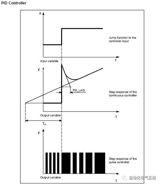
Therefore, it is very important to master the type and characteristics of the control system. (Figure 1, Figure 2, Figure 3, Figure 4)
figure 1
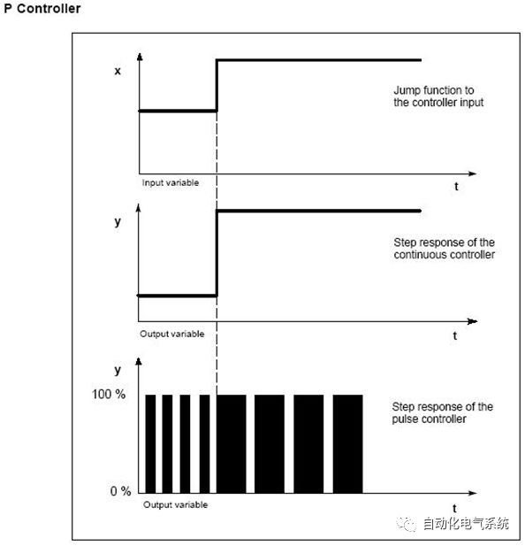
figure 2
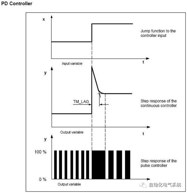
image 3

Figure 4
2 PID system controller selection
The properties of the control system are determined by the technical process and the machine conditions. Therefore, in order to obtain a good control effect, you must choose the most suitable system controller.
2.1 continuous controller, switch controller
Continuous controller, output a linear (analog) value.
Switch controller, output a binary (digital) value.
2.2 Fixed value controller
Fixed value control, process control using a set fixed value, only occasionally modify the reference variable, process deviation control.
2.3 cascade controller
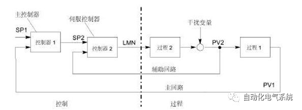
Cascade controller, controller serial connection control. The first controller (master controller) determines the setpoint of the serial controller (slave controller) or the actual error affector setpoint based on the process variable.
The control performance of a cascaded controller can be improved using other process variables. For this purpose, an auxiliary process variable PV2 (output of the main controller SP2) can be added to the main control variable. The master controller may apply the process variable PV1 to the set point SP1 and may adjust SP2 so as to reach the target as quickly as possible without overshoot. (Figure 5)
Figure 5
2.4 Hybrid Controller
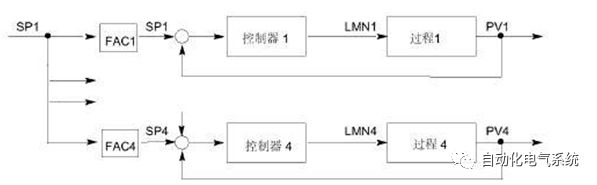
The hybrid controller is a control structure that calculates the total number of SPs based on the total number of set points required for each controlled component. Here, the sum of the mixing coefficients FAC must be "1". (Figure 6)
Figure 6
2.5 Proportional Controller
2.5.1 Single-cycle proportional controller
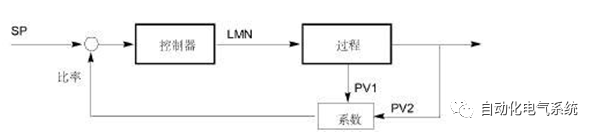
A single-cycle proportional controller can be used where "the ratio between two process variables" is more important than the "absolute value of two process variables". (For example, speed control). (Figure 7)
Figure 7
2.5.2 Multi-cycle proportional controller
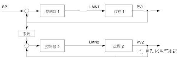
For multi-cycle proportional control, the ratio of the two process variables PV1 and PV2 remains constant. Therefore, you can use the process value of the first control cycle to calculate the setpoint of the second control cycle. For the dynamic change of the process variable PV1, it is also guaranteed to maintain a specific ratio. (Figure 8)
Figure 8
2.6 Level Controller
A secondary controller can only capture two output states (for example, on and off). The typical control is: a heated system, pulse width modulation output through the relay.
2.7 three-level controller
A three-level controller can only collect three specific output states. We need to distinguish between "pulse width modulation" (eg, heating-cooling, heating-off-cooling) and "stepping control using an integrated actuator" (eg, left-stop-right).
3 wiring
For integrated I/O controllers, you must use additional I/O modules.
3.1 Wiring rules
3.1.1 Connection cable
For digital I/O, shielded cables must be used if the line is 100 meters long;
Cable shielding must be grounded at both ends;
The cross-sectional area of ​​the flexible cable is 0.25...1.5 mm2.
No need to choose a cable jacket. If you decide to choose a cable jacket, you can use a cable jacket without insulation rings (DIN 46228, Shape A, Short version);
3.1.2 shield termination components
You can use shielded termination components to ground all shielded cables directly through the rails;
The components must be wired in the event of a power failure;
3.1.3 Warning
Live work can be life-threatening.
There is a risk of electric shock if you wire the front plug of the component with live power!
3.1.4 Other Information
Additional notes can be found in the "CPU Data" manual and the CPU installation manual.
4 parameter assignment tool introduction
With the help of "PID parameter setting" tool, you can easily debug the parameters of the function blocks SFB41/FB41 and SFB42/FB42 (background data blocks).
4.1 User Interface for Debugging PID Parameters
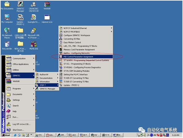
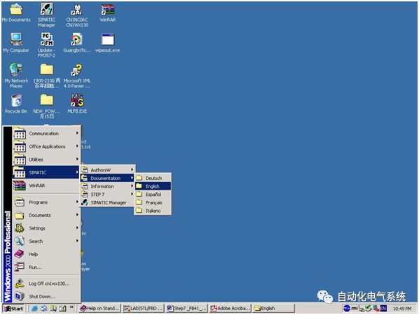
In the Windows operating system, the operation procedure for calling the "Debug PID Parameter User Interface" is as follows:
Start> SIMATIC> STEP7> PID Control Parameter Assignment (see Figure 9).
Figure 9
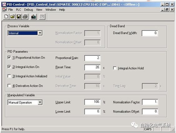
In the initial dialog, you can open an existing instance block of FB41/SFB41 "CONT_C" or FB42/SFB42 "CONT_S". It is also possible to generate a new data block which can then be assigned to the FB41 / SFB41 "CONT_C" or FB42 / SFB42 "CONT_S" as an instance data block. (Figure 10)
Figure 10
FB43/SFB43 "PULSEGEN" User interface tools without parameter settings. You must set its parameters in STEP 7.
4.2 Ways to Get Online Help
When assigning parameters to FB41 / SFB41 "CONT_C", FB42 / SFB42 "CONT_S" or FB43 / SFB43 "PULSEGEN", you can get help with the following three ways:
· Use Step7 menu Help>Contents to get corresponding help information;
· Get ​​help by pressing the F1 key;
· In the PID parameter setting dialog, click Help to get specific help information.
5 in the user program
The following sections will help you design a user program based on your application.
5.1 Calling Function Blocks
The system function block is called with the corresponding instance data block.
Example: CALL SFB 41, DB30 (or, CALL FB 41, DB 31)
5.2 Background data blocks
The parameters of the system function block are saved in the instance data block. Chapter 6 describes these parameters.
You can access these parameters in the following ways
· DB number and offset address
· Data block number and symbol address in data block
5.3 Program Structure
The SFB must be called in the restart organization block OB100 and in the cyclic interrupt organization block OB30...38.
mode:
· OB100 Call SFB/FB 41,42,43, DB 30
· OB35 Call SFB/FB 41,42,43, DB 30
6 Function Block Introduction
6.1 Continuous adjustment function SFB 41/FB 41 "CONT_C"
6.1.1 Introduction
The SFB/FB "CONT_C" (Continuous Controller) is used to control technological processes in the SIMATIC S7 control system using continuous I/O variables. You can control the system by turning the PID controller on or off with parameters. This can be easily done with the parameter assignment tool. Call: Start> SIMATIC> STEP 7> PID Control Parameter Assignment (pictured). On-line e-Manual, see Start> SIMATIC> Documentation> English> STEP 7 – PIDControl (Figure 11).
Figure 11
6.1.2 Applications
You can use the controller as a stand-alone PID fixed-point controller or as a cascade controller, hybrid controller, and proportional controller in multi-cycle control. The function of the controller is based on the PID control algorithm of the sampling controller with an analog signal. If necessary, it can be expanded by a pulse transmitter (PULSEGEN) to generate a pulse width modulated output signal to control the proportional actuator. Or three step controllers.
6.1.3 Description
In addition to the functions of setpoint operation and process numerical operation, the SFB41/FB 41 (CONT_C) can use a continuous variable output and a manual influence control value option to implement a complete PID controller. The following is a detailed sub-function description of SFB 41/FB41 (CONT_C):
6.1.3.1 Setpoint operation
Setpoints are input in "SP_INT" in floating-point format.
6.1.3.2 Actual numerical operations
Process variables can be entered in either the peripheral (I/O) or floating-point numerical format. The "CRP_IN" function converts the value of the "PV_PER" peripheral into a floating-point format value between -100 and +100%. The conversion formula is as follows:
Output of CPR_IN=PV_PER x100 /27648
The "PV_NORM" function can standardize the output of "CRP_IN" according to the following rules:
Output PV_NORM = (output of CPR_IN) x PV_FAC + PV_OFF
The default value of "PV_FAC" is "1", and the default value of "PV_OFF" is "0".
The variables "PV_FAC" and "PV_OFF" are the result of the conversion of the following formula:
PV_OFF = (output of PV_NORM) - (output of CPR_IN) x PV_FAC
PV_FAC = (output of PV_NORM) - PV_OFF) / (output of CPR_IN)
It does not have to be converted to a percentage value. If the set point is physically determined, the actual value can also be converted to the physical value.
6.1.3.3 Negative Deviation Calculation
The difference between the set point and the actual value results in a negative deviation. In order to suppress small, constant oscillations due to the quantification of the controlled quantity (for example pulse width modulation using PULSEGEN), a dead band (DEADBAND) is applied in the dead zone. If DEADB_W = 0, the deadband is closed.
6.1.3.4 PID algorithm
The PID algorithm is controlled as a positional algorithm. Proportional operations, integral operations (INT), and derivative operations (DIF) can all be connected in parallel, or they can be activated or canceled individually. This allows configuration to P, PI, PD, and PID controllers. It can also be a pure I and D regulator.
6.1.3.5 Manual Mode
You can switch between manual mode and automatic mode. In manual mode, the controlled variable is modified to a manually selected value.
The integrator (INT) is internally set to "LMN-LMN_P-DISV", the microprocessor (DIF) is internally set to "0", and internally matched. This means that switching to automatic mode does not cause a sudden change in the controlled variable.
6.1.3.6 Handling of Controlled Values
With the LMNLIMIT function, controlled values ​​can be limited to a selected value. When the input variable exceeds the limit, the signal bit will indicate. The "LMN_NORM" function can normalize the output of "LMNLIMIT" according to the following formula:
LMN = (output of LMNLIMIT) x LMN_FAC +LMN_OFF
The default value of "LMN_FAC" is "1", and the default value of "LMN_OFF" is "0".
Controlled values ​​also apply to the peripheral device (I/O) format. The "CPR_OUT" function can convert the floating-point value "LMN" to a peripheral value. The conversion formula is as follows:
LMN_PER = LMN x2764/10
6.1.3.7 Feedforward control
A disturbance variable is introduced into the "DISV" input.
6.1.3.8 Initialization
SFB 41/FB 41 "CONT_C" has an initialization program that can be executed when the input parameter COM_RST = TRUE is set. During initialization, the integrator can be internally set to the initial value "I_ITVAL". If it is called at a cyclic interrupt priority, it will continue to run from this value. All other outputs are set to their default values.
6.1.3.9 Error Information
The fault output parameter RET_VAL is not used.
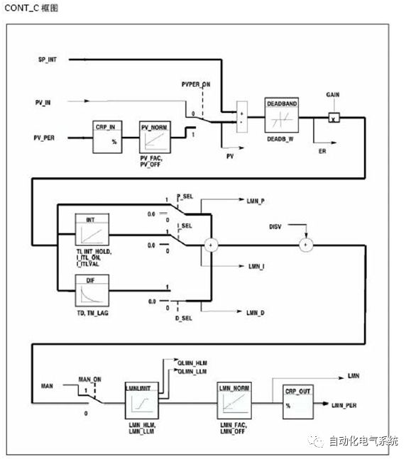
6.1.3.10 SFB/FB "CONT_C" (Continuously Tuning Controller) Block Diagram
As shown in Figure 12.
Figure 12
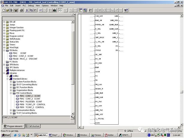
6.1.3.11 Input Parameters
SFB 41/FB 41 "CONT_C" (Figure 13)
Figure 13
The following table shows the description of the SFB 41/FB 41 "CONT_C" input parameters:
| No. | parameter | type of data | Range of values | default | Instructions |
| 1 | COM_RST | BOOL | FAULSE | COMPLETE RESTART. The block has an initialization program that can be run when the input parameter COM_RST is set. | |
| 2 | MAN_ON | BOOL | TRUE | MANUAL VALUE ON If the input "manual value close" is set, the closed loop control cycle is interrupted. The manual value is set to the controlled value. | |
| 3 | PVPER_ON | BOOL | FALSE | PROCESS VARIABLE PERIPHERY ON/(process variable peripheral is on) If the process variable is read from the I/O, the input "PV_PER" must be connected to the peripheral device. And enter "PROCESS VARIABLE PERIPHERY ON" must be set. | |
| 4 | P_SEL | BOOL | TRUE | PROPORTIONAL ACTION ON (proportional component ON) The PID components can be individually activated or deactivated in the PID algorithm. When the input "proportional component on" is set, the P component is switched on. | |
| 5 | I_SEL | BOOL | TRUE | INTEGRAL ACTION ON The PID components can be individually activated or deactivated in the PID algorithm. When the "integral component on" input is set, the I component is turned on. | |
| 6 | INT_HOLD | BOOL | FALSE | INTEGRAL ACTION HOLD (integral component hold) The integrator output is frozen. To do this, the input "Integral Action Hold" must be set. | |
| 7 | I_ITL_ON | BOOL | FALSE | INITIALIZATION OF THE INTEGRAL ACTION (Integral component initialization turned on) The output of the integrator can be set to the input "I_ITLVAL". To do this, the input "initialization of the integral operation" must be set. | |
| 8 | D_SEL | BOOL | FALSE | DERIVATIVE ACTION ON (differential component ON) The PID components can be individually activated or deactivated in the PID algorithm. When the input "differential component on" is set, the D component is turned on. | |
| 9 | CYCLE | TIME | >=1ms | T#1s | SAMPLE TIME (sampling time) The time between block calls must be constant. The “sample time†input specifies the time between block calls and should be consistent with the OB35 set time. |
| 10 | SP_INT | REAL | -100.0 to +100.0 (%) or physical value 1 | 0.0 | INTERNALSETPOINT (internal set point) The "internal setpoint" input is used to determine the setpoint. |
| 11 | PV_IN | REAL | -100.0 to +100.0 (%) or physical value 1 | 0.0 | PROCESSVARIABLE IN (process variable input) You can set an initial value to the "process variable input" input or an external process variable in a floating-point format. |
| 12 | PV_PER | WORD | W#16#0000 | PROCESS VARIABLE PERIPHERY (Process Variable Peripheral) The actual value of the peripheral device is connected to the "Process Variable Peripheral" input via a process variable in I/O format, connected to the controller | |
| 13 | MAN | REAL | -100.0 to +100.0 (%) or physical value 2 | 0.0 | MANUAL VALUE (manual value) The "manual value" input can be used to set a manual value via the operator interface function. |
| 14 | GAIN | REAL | 2.0 | PROPORTIONAL GAIN (proportional gain) The "proportional gain" input can set the controller's proportional gain factor. | |
| 15 | TI | TIME | >=CYCLE | T#20s | RESET TIME (reset time) The "reset time" input determines the time response of the integrator. |
| 16 | TD | TIME | >=CYCLE | T#10s | DERIVATIVE TIME (differential time) The "differential time" input determines the time response of the derivative unit. |
| 17 | TM_LAG | TIME | >=(CYCLE/2) | T#2s | TIME LAG OF THE DERIVATIVE ACTION (differential component lag time) The algorithm for the derivative operation includes a time lag that can be assigned to the "delay time of the derivative component" input. |
| 18 | DEADB_W | REAL | >=0.0(%) or physical value 1 | 0.0 | DEAD BAND WIDTH Deadband is used to store errors. The "Dead Bandwidth" input determines the size of the dead zone. |
| 19 | LMN_HLM | REAL | LMN_LLM to 100.0 (%) or physical value 2 | 100.0 | MANIPULATED ALUE HIGH LIMIT (upper limit of manipulated value) The controlled value must have an "upper limit" and a "lower limit". The "controlled upper limit" input determines the "upper limit". |
| 20 | LMN_LLM | REAL | -100.0 (%) to LMN_HLM or physical value 2 | 0.0 | MANIPULATED VALUE LOW LIMIT (lower limit of manipulated value) The controlled value must have an "upper limit" and a "lower limit". The "Lower limit" is defined at the "Lower limit of manipulated value" input. |
| twenty one | PV_FAC | REAL | 1.0 | PROCESS VARIABLE FACTOR (process variable factor) The "Process Variable Coefficient" input is used to multiply the process variable. This input can be used to match the process variable range. | |
| twenty two | PV_OFF | REAL | 0.0 | PROCESSVARIABLE OFFSET (process variable offset) The "process variable offset" input can be added to the "process variable". This input can be used to match the range of process variables. | |
| twenty three | LMN_FAC | REAL | 1.0 | MANIPULATED VALUE FACTOR (controlled numerical coefficient) The "Controlled coefficient" input is used to multiply the controlled value. This input can be used to match the range of controlled values. | |
| twenty four | LMN_OFF | REAL | 0.0 | MANIPULATED VALUE (controlled value offset) The "Controlled Value Offset" can be added to the controlled value. This input can be used to match the range of controlled values. | |
| 25 | I_ITLVAL | REAL | -100.0 to +100.0 (%) or physical value 2 | 0.0 | INITIALIZATION VALUE OF THE INTEGRAL-ACTION (integral component initialization value) The output of the integrator can be set with input "I_ITL_ON". The initialization value can be set to the "integral component initial value" input. |
| 26 | DISV | REAL | -100.0 to +100.0 (%) or physical value 2 | 0.0 | DISTURBANCE VARIABLE (disturbance variable) For feedforward control, the disturbance variable is connected to the "disturbance variable" input. |
1) The parameters in "setpoint channel" and "process variable channel" should have the same unit. For example, if PV_IN is used as "process physical value" or "process physical value percentage", SP_INT must use the same unit; if PV_PER is used as the actual value of the peripheral device, SP_INT can only use "-100.0 to +100.0 (%) "As a setting value. If the setting value is 8Mpa in SP_INT is 0~10Mpa, then need to fill in 0.8, PV_PER fill in the hardware peripheral address IW XXX;
2) The parameters in the controlled quantity channel should have the same unit.
6.1.3.12 Output Parameters
The following table shows the description of the SFB 41/FB 41 "CONT_C" output parameters:
| No. | parameter | type of data | Range of values | default | Instructions |
| 1 | LMN | REAL | 0.0 | MANIPULATED VALUE (controlled value) Valid controlled values ​​are output in floating-point format at the "controlled value" output. | |
| 2 | LMN_PER | WORD | W#16#0000 | MANIPULATEDVALUE PERIPHERY (Controlled Numerical Peripherals) Controlled values ​​in the I/O format are connected to the controller on the output of the "Controlled Value Peripherals". | |
| 3 | QLMN_HLM | BOOL | FALSE | HIGH LIMIT OF MANIPULATED VALUE REACHED The manipulated value must specify a maximum limit and a minimum limit. "Achieving a controlled upper limit of numerical value" indicates that the maximum limit has been exceeded. | |
| 4 | QLMN_LLM | BOOL | FALSE | LOW LIMIT OF MANIPULATED VALUE REACHED (To reach the lower limit of the controlled value) The controlled value must specify a maximum limit and a minimum limit. "Arrival limit reached controlled" indicates that the minimum limit has been exceeded. | |
| 5 | LMN_P | REAL | 0.0 | PROPORTIONALITY COMPONENT (proportional component) The "proportional component" output outputs the proportional component of the manipulated value. | |
| 6 | LMN_I | REAL | 0.0 | INTEGRAL COMPONENT The "integral component" output outputs the integral component of the manipulated value. | |
| 7 | LMN_D | REAL | 0.0 | DERIVATIVE COMPONENT (differential component) The "differential component" output outputs the derivative component of the controlled value. | |
| 8 | PV | REAL | 0.0 | PROCESS VARIABLE (process variable) The effective process variable is output at the "process variable" output. | |
| 9 | ER | REAL | 0.0 | ERROR SIGNAL The effective error is output at the "error signal" output. |
6.2 Step control function SFB 42/FB 42 "CONT_S"
6.2.1 Introduction
The SFB/FB "CONT_S" (step controller) is used on the SIMATIC S7 programmable controller for the control technology process of the binary numerical control numerical output signal integral actuator. During parameter assignment, you can activate or deactivate PI step controller sub-functions to match the controller to the process. This can be easily done with the parameter assignment tool. Call: Start> SIMATIC> STEP 7> PID Control Parameter Assignment (pictured). Online electronic manual, see Start> SIMATIC> Documentation> English> STEP 7 – PIDControl (pictured).
6.2.2 Applications
You can use this controller as a separate PI fixed setpoint controller, or as a cascade controller, hybrid controller, or proportional controller in an auxiliary control loop (second stage closed loop), but it cannot be used as a master control (first stage regulator). The function of the controller is based on the PI controller algorithm of the sampling controller. The binary output signal is generated from the analog execution signal.
The following functions apply to the FB V1.5 or V1.1.0 or later of the CPU 314 IFM:
With TI = T#0 ms, the integral component of the regulator can be blocked. Therefore, the function block is allowed to act as a proportional (P) controller.
Since the controller does not use any position feedback signal, internally calculated controlled variables will not accurately match the position of the signal control element. If the controlled variable (ER*GAIN) is negative, adjustments should be made. The regulator then sets the output QLMNDN (controlled quantity signal low) until LMNR_LS (position feedback signal low limit) is set.
The controller can also be used as a secondary controller (second actuator) in a controller cascade. The setpoint input "SP_INT" is used to assign the position of the control element. In this case, the actual value input and the parameter "TI (integration time)" must be set to "0". An application example: The temperature is controlled by an electronically controlled valve flap, which is the control of the temperature of the heat output by means of a binary pulse digital output signal and the use of valves to control the cooling capacity. In this case, the controlled variable (ER*GAIN) should have a negative value in order to fully close the valve.
6.2.3 Description
In addition to the function of the process data channel, the SFB/FB "CONT_S" (step controller) can use a digitally controlled value output and manually influence the control value option to implement a complete PI controller. The step controller does not use position feedback signals. The limit signal can be used to limit the pulse output. Below you can find detailed sub-function descriptions:
6.2.3.1 Setpoint operation
The setpoint is entered in floating-point format at the "SP_INT" input.
6.2.3.2 Actual numerical operations
Process variables can be entered in either the peripheral (I/O) or floating-point format. The "CRP_IN" function converts the value of the "PV_PER" peripheral into a floating-point format value between -100 and +100%. The conversion formula is as follows:
Output of CPR_IN=PV_PER x100/27648
The "PV_NORM" function can standardize the output of "CRP_IN" according to the following formula:
Output of PV_NORM = (output of CPR_IN) x PV_FAC + PV_OFF
The default value of PV_FAC is "1" and the default value of PV_OFF is "0".
The variables "PV_FAC" and "PV_OFF" are the result of the conversion of the following formula:
PV_OFF = (output of PV_NORM) - (output of CPR_IN) x PV_FAC
PV_FAC = ((output of PV_NORM) - PV_OFF)/(output of CPR_IN)
6.2.3.3 Negative Deviation Calculation
The difference between the set point and the actual value results in a negative deviation. In order to suppress small, constant oscillations due to the quantification of the controlled variable (e.g., fluctuations of the controlled value due to the actuator valve), a deadband is set for the negative deviation (DEADBAND). If DEADB_W = 0, the dead zone will be closed.
6.2.3.4 PI Stepping Algorithm
The SFB/FB "CONT_S" (step controller) does not use the position feedback signal. The integral operation of the PI algorithm and the assumed position feedback signal are both calculated in the integrator (INT) and compared with the remaining P operation as a feedback value. The difference is used for a three-step element (THREE_ST) and a pulse generator (PULSEOUT) to generate the actuator control pulses. The switching frequency of the controller can be reduced by using threshold control on three step elements.
6.2.3.5 Feedforward control
A disturbance variable was introduced into the "DISV" input.
6.2.3.6 Initialization operation
The SFB/FB "CONT_S" (step controller) has an initialization program that can be run when the input parameter COM_RST = TRUE is set. All other outputs are set to their default values.
6.2.3.7 Error Messages
The fault output parameter RET_VAL is not used.
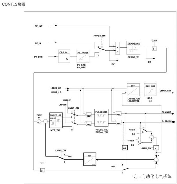
6.2.3.8 SFB/FB "CONT_S" (Step Controller) block diagram
Figure 14
Figure 14
6.2.3.9 Input parameters
SFB 42/FB 42 "CONT_S" (Figure 15)
Figure 15
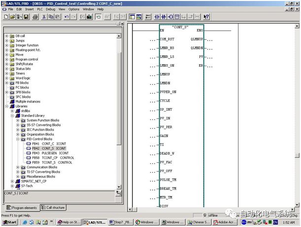
The following table shows the description of the SFB 42/FB 42 "CONT_S" input parameters:
| No. | parameter | type of data | Range of values | default | Instructions |
| 1 | COM_RST | BOOL | FAULSE | COMPLETE RESTART. The block has an initialization program that can be run when the input parameter COM_RST is set. | |
| 2 | LMNR_HS | BOOL | FALSE | HIGH LIMIT OF POSITION FEEDBACK SIGNAL The "actuator at high limit stop" signal is connected to the "position feedback signal high limit" input. LMNR_HS = TRUE indicates that the actuator is at its maximum limit. | |
| 3 | LMNR_LS | BOOL | FALSE | LOW LIMIT OF POSITION FEEDBACK SIGNAL The "actuator at low stop" signal is connected to the "position feedback signal low limit" input. LMNR_LS = TRUE indicates that the actuator is at its lower limit. | |
| 4 | LMNS_ON | BOOL | TRUE | MANUAL ACTUATING SIGNALS ON The signal processing is switched to manual mode by "manual execution signal ON". | |
| 5 | LMNUP | BOOL | FALSE | ACTUATING SIGNALS UP By executing the signal manually, the output signal "QLMNUP" is set at the "execute signal rising edge" input. | |
| 6 | LMNDN | BOOL | FALSE | ACTUATING SIGNALS DOWN By executing the signal manually, the output signal "QLMNDN" is set at the "Execute signal falling edge" input. | |
| 7 | PVPER_ON | BOOL | FALSE | PROCESS VARIABLE PERIPHERY ON (process variable peripheral is on) If the process variable is read from the I/O, the input "PV_PER" must be connected to the peripheral device and the input "PROCESS VARIABLE" PERIPHERY ON" must be set. | |
| 8 | CYCLE | TIME | >=1 ms | T#1s | SAMPLING TIME (sampling time) The time between block calls must be constant. The "Sampling Time" input specifies the time between block calls. |
| 9 | SP_INT | REAL | -100.0 to +100.0 (%) or physical value 1 | 0.0 | INTERNAL SETPOINT (internal set value) The "Internal setpoint" input is used to determine a setpoint. |
| 10 | PV_IN | REAL | -100.0 to +100.0 (%) or physical value 1 | 0.0 | PROCESS VARIABLE IN (process variable input) You can set an initial value to the "process variable input" input or an external process variable in a floating-point format. |
| 11 | PV_PER | WORD | W#16#0000 | PROCESS VARIABLE PERIPHERY (Process Variable Peripheral) Process variables in the I/O format are connected to the "Process variable peripheral" input of the controller. | |
| 12 | GAIN | REAL | 2.0 | PROPORTIONAL GAIN (proportional gain) The "proportional gain" input sets the gain of the controller. | |
| 13 | TI | TIME | >=CYCLE | T#20s | RESET TIME (reset time) The "reset time" input determines the time response of the integrator. |
| 14 | DEADB_W | REAL | 0.0 to +100.0 (%) or physical value 1 | 1.0 | DEAD BAND WIDTH The deadband is used for errors. "Dead width" is used to determine the size of the dead zone. |
| 15 | PV_FAC | REAL | 1.0 | PROCESS VARIABLE FACTOR (process variable factor) The "Process variable factor" input is used to multiply the process variable. This input can be used to match the range of process variables. | |
| 16 | PV_OFF | REAL | 0.0 | PROCESS VARIABLE OFFSET (process variable offset) The "process variable offset" input is added to the process variable. This input is used to match the range of process variables. | |
| 17 | PULSE_TM | TIME | >=CYCLE | T#3 s | MINIMUM PULSE TIME The minimum pulse width can be assigned using the parameter "Minimum pulse time". |
| 18 | BREAK_TM | TIME | >=CYCLE | T#3 s | MINIMUM BREAK TIME The minimum pulse interval time can be assigned using the parameter "minimum interval time". |
| 19 | MTR_TM | TIME | >=CYCLE | T#30 s | MOTOR MANIPULATED VALUE (electric execution time) The time required for the actuator to move from one limiting position to the other limiting position can be entered in the parameter “motor execution time†parameter. |
| 20 | DISV | REAL | -100.0 to +100.0 (%) or physical value 2 | 0.0 | DISTURBANCE VARIABLE (disturbance variable) For feedforward control, the disturbance variable is connected to the input "disturbance variable". |
3) The parameters in "setpoint channel" and "process variable channel" should have the same unit;
4) The parameters in the controlled quantity channel should have the same unit.
6.2.3.10 Output Parameters
The following table shows the description of the SFB 42/FB 42 "CONT_S" output parameters:
| No. | parameter | type of data | Range of values | default | Instructions |
| 1 | QLMNUP | BOOL | FALSE | ACTUATING SIGNAL UP (execution signal rise) If the "Execute signal rise" output is set, the execution valve is open. | |
| 2 | QLMNDN | BOOL | FALSE | ACTUATING SIGNAL DOWN If the "Execute signal drop" output is set, the execution valve is open. | |
| 3 | PV | REAL | 0.0 | PROCESS VARIABLE (process variable) The effective process variable is output at the "process variable" output. | |
| 4 | ER | REAL | 0.0 | ERROR SIGNAL (negative deviation signal) The effective negative deviation value is output at the "negative deviation signal" output. |
6.3 Pulse Width Modulator SFB 43/FB 43 "PULSEGEN"
6.3.1 Introduction
The SFB/FB "PULSEGEN" (pulse generator) can be used to use the proportional actuator's pulse output for the PID controller. Online electronic manual, see Start> SIMATIC> Documentation> English> STEP 7 – PIDControl (see figure).
6.3.2 Applications
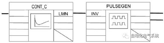
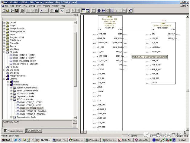
With the SFB/FB "PULSEGEN" (pulse generator), a PID two-step or three-step controller can be configured with pulse width modulation. This function is generally used with the continuous controller SFB/FB "CONT_C". (Figure 16)
Figure 16
6.3.3 Description
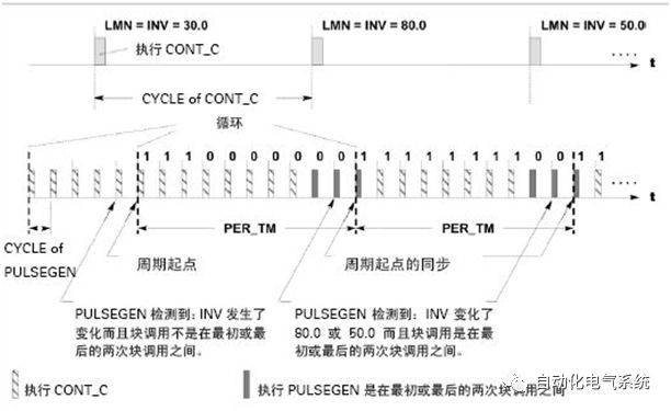
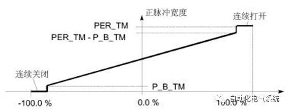
The function "PULSEGEN" can be used to convert the input variable "INV" (=LMN of the PID controller) into a pulse train with a constant period by modulating the pulse width. This constant cycle corresponds to the cycle time of the input variable refresh and must be at "PER_TM" Assignment.
The pulse width of each cycle is proportional to the input variable. The cycle time in "PER_TM" is different from the processing time of SFB/FB "PULSEGEN". The "PER_TM" cycle time is the sum of the loops executed by the multiple SFB/FB "PULSEGEN". Therefore, the number of SFB/FB "PULSEGEN" calls per "PER_TM" cycle is the pulse width, and the pulse width can be accurately measured. The minimum controlled value is determined in the parameter "P_B_TM". (Figure 17)
Figure 17
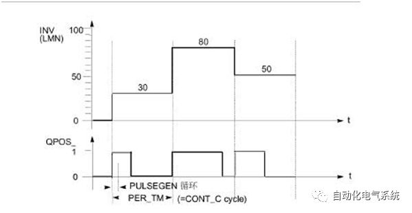
6.3.3.1 Pulse Width Modulation
The input variable is 30% and the SFB/FB "PULSEGEN" is called 10 times per PER_TM cycle time, which means the following:
• For the first three SFB/FB "PULSEGEN" (30% of 10 calls), the output "QPOS" is "1"
• For the remaining 7 SFBs/FBs "PULSEGEN" (70% of 10 calls), the output "QPOS" is "0"
6.3.3.2 SFB/FB "PULSEGEN" block diagram
See Figure 18.
Figure 18
6.3.3.3 Accuracy of Controlled Values
If the "Sampling Frequency Scale" is 1:10 (ratio of "CONT_C" call to "PULSEGEN" call), the precision of the manipulated value is reduced to 10% in this example. In other words, the set input value "INV" can only be converted to pulse width in "10%" steps at the "QPOS" output.
The accuracy can be improved only if the number of "PULSEGEN" calls in each "CONT_C" call increases.
For example, if the number of "PULSEGEN" calls for each "CONT_C" call is 100, the resolution of the manipulated value will reach 1% (recommended resolution <= 5%).
note
The "Sampling Frequency Scale" must be programmed by the user.
6.3.3.4 Automatic Synchronization
The block that refreshes the input variable "INV" (for example, "CONT_C") can be automatically synchronized with the pulse output. This ensures that a change in the input variable can be output as a pulse as quickly as possible.
The pulse generator can periodically evaluate the input value "INV" according to the period of "PER_TM" and convert the value into a pulse signal of a corresponding length.
However, since "INV" is generally calculated in the slow cyclic interrupt level, the pulse generator should convert the specific value to a pulse signal as soon as possible after the "INV" is refreshed.
To do this, the block must be synchronized to the beginning of the cycle using the following procedure:
If "INV" changes and the block call is not in the first or last two call cycles of a cycle, synchronization can occur. The pulse width will be recalculated and a new cycle will be output in the next cycle. (Figure 19)
Figure 19
Automatic synchronization can be turned off based on the "SYN_ON" (= FALSE) input.
note
At the beginning of a cycle, the image of the previous value of "INV" (ie, LMN) will be more or less mixed into the pulse signal.
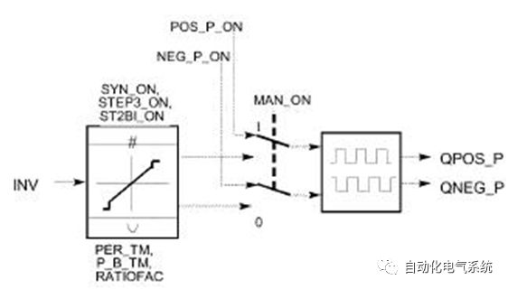
6.3.3.5 PID Controller Output Operating Mode
Depending on the parameters assigned to the pulse generator, the PID regulator can be configured to have a three-stage output or a two-way or one-way two-pole output PID controller. The following table shows the switch combination settings for the possible modes:
| mode | MAN_ON | STEP3_ON | ST2BI_ON |
| Three-level adjustment | FALSE | TRUE | ANY |
| Two-stage adjustment with two-way adjustment zone (-100%...+100%) | FALSE | FALSE | TRUE |
| Two-stage adjustment with unidirectional adjustment zone (0...+100%) | FALSE | FALSE | FALSE |
| Manual mode | TRUE | ANY | ANY |
6.3.3.5.1 Three-level control
In the "three-level control" mode, three states of the control signal can be generated. The values ​​of the binary output signals "QPOS_P" and "QNEG_P" can be assigned to the state of the actuator.
The following table shows an example of temperature control:
| output signal | heating | Actuator off | Refrigeration |
| QPOS_P | TRUE | FLASE | FLASE |
| QNEG_P | FLASE | FLASE | TRUE |
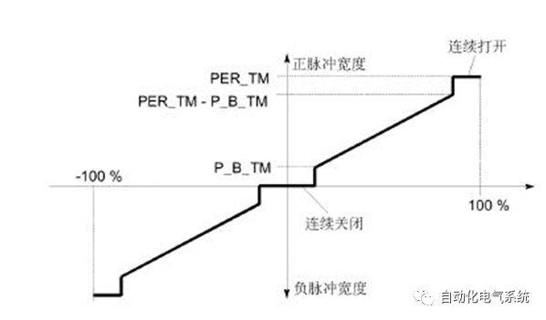
Based on the input variables, the pulse width can be calculated using a characteristic curve. The shape of the characteristic curve depends on the minimum pulse time or the maximum interruption time and the proportionality factor.
The normal value of the scale factor is "1".
The "knee" in the curve is due to the minimum pulse time or the minimum interruption time.
Minimum pulse or minimum interval
The correct assignment of the minimum pulse or the minimum interruption time "P_B_TM" prevents a short breaking time and reduces the service life of switching elements and actuators.
note
Otherwise, the smaller absolute value of the input variable "LMN" which can generate a pulse width shorter than "P_B_TM" is deleted. Large input values ​​that can generate pulse widths greater than "PER_TM-P_B_TM" are set to 100 % or -100 %.
The positive pulse width and negative pulse width can be calculated by multiplying the input variable (unit [%]) and the cycle time.
Pulse period = INV / 100 xPER_TM
The following figure (Figure 20) shows the system curve of a three-level controller (scale factor = 1):
Figure 20
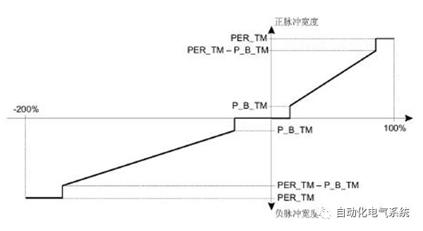
Using the scale factor "RATIOFAC", the ratio of positive pulse width to negative pulse width can be changed.例如,对于çƒå¤„ç†ï¼Œè¿™å¯ç”¨äºŽä½¿ç”¨ä¸åŒçš„æ—¶é—´å¸¸æ•°åŠ çƒå’Œå†·å´æ‰§è¡Œæœºæž„。
比例系数也会影å“最å°è„‰å†²/æš‚åœå‘¨æœŸã€‚比例系数< 1æ„æ€æ˜¯æŒ‡è´Ÿè„‰å†²çš„阈值乘以比例系数。
比例系数 < 1
通过输入数值乘以脉冲周期所计算的比例系数,å¯ä»¥å‡å°‘负脉冲输出的脉冲周期。
æ£è„‰å†²å‘¨æœŸ= INV/100 xPER_TM
负脉冲周期= INV/100 xPER_TM x RATIOFAC
下图(如图21)所示为一个三级控制器的系统曲线(比例系数=0.5):
图 21
比例系数 > 1
通过输入数值乘以脉冲周期所计算的比例系数,å¯ä»¥å‡å°‘æ£è„‰å†²è¾“出的脉冲周期。
负脉冲周期=INV/100 xPER_TM
æ£è„‰å†²å‘¨æœŸ=INV/100 xPER_T/ RATIOFAC
6.3.3.5.2二级控制
对于二级控制,åªèƒ½å°†PULSEGENçš„æ£è„‰å†²è¾“出“QPOS_Pâ€è¿žæŽ¥åˆ°I/Oæ‰§è¡Œæœºæž„ã€‚æ ¹æ®æ‰€ä½¿ç”¨çš„å—控数值范围,二级控制器å¯ä»¥æœ‰ä¸€ä¸ªåŒæžæˆ–å•æžå—控数值范围。
6.3.3.5.2.1 两级调节,带åŒå‘调节区(-100%…+100%)
图 22
6.3.3.5.2.2 两级调节,带å•å‘调节区(0…+100%)
图 23

如果控制循环ä¸äºŒçº§æŽ§åˆ¶å™¨çš„连接需è¦ä¸€ä¸ªæ‰§è¡Œè„‰å†²çš„逻辑转æ¢äºŒè¿›åˆ¶ä¿¡å·ï¼Œå¯ä»¥åœ¨â€œQNEG_Pâ€å°†è¾“出信å·è¿›è¡Œâ€œéžâ€è¿ç®—。
| 脉冲 | 执行机构打开 | æ‰§è¡Œæœºæž„å…³é— |
| QPOS_P | TRUE | FALSE |
| QNEG_P | FALSE | TRUE |
6.3.3.5.3二级控制或三级控制ä¸çš„手动模å¼
在手动模å¼ï¼ˆMAN_ON = TRUE)ä¸ï¼Œä¸‰çº§æŽ§åˆ¶å™¨æˆ–二级控制器的二进制输出å¯ä»¥ä½¿ç”¨ä¿¡å·
“POS_P_ONâ€å’Œâ€œNEG_P_ONâ€ä»¥åŠâ€œINVâ€è¿›è¡Œè®¾ç½®ã€‚
| POS_P_ON | NEG_P_ON | QPOS_P | QNEG_P | |
| 三级调节 | FALSE | FALSE | FALSE | FALSE |
| TURE | FALSE | TRUE | FALSE | |
| FALSE | TRUE | FALSE | TRUE | |
| TRUE | TRUE | FALSE | FALSE | |
| 二级调节 | FALSE | Any | FALSE | TRUE |
| TRUE | Any | TRUE | FALSE |
6.3.3.6åˆå§‹åŒ–
SFB“PULSGENâ€æœ‰ä¸€ä¸ªåˆå§‹åŒ–程åºï¼Œå¯ä»¥åœ¨è¾“å…¥å‚æ•°COM_RST= TRUEç½®ä½ æ—¶è¿è¡Œã€‚
所有信å·éƒ½è¢«è®¾ç½®ä¸ºâ€œ0â€ã€‚
6.3.3.7出错信æ¯
故障输出å‚æ•°RET_VALä¸ä½¿ç”¨ã€‚
6.3.3.8输入å‚æ•°
SFB 43/FB 43“PULSEGENâ€ï¼ˆå¦‚图24)
图 24
下表列出SFB 43/FB 43“PULSEGENâ€è¾“å…¥å‚数的说明:
| No. | å‚æ•° | æ•°æ®ç±»åž‹ | 数值范围 | ç¼ºçœ | Instructions |
| 1 | INV | REAL | -100.0...100.0 (%) | 0.0 | INPUT VARIABLE(输入å˜é‡ï¼‰ 模拟å—控é‡è¿žæŽ¥åˆ°è¾“å…¥å‚数“输入å˜é‡â€ • 对于RATIOFAC <1 的三级控制 • 对于RATIOFAC >1 的三级控制 • 对于åŒæžäºŒçº§æŽ§åˆ¶ • 对于多æžäºŒçº§æŽ§åˆ¶ |
| 2 | PER_TM | TIME | >=20*CYCLE | T#1s | PERIOD TIME(周期时间) 脉冲宽度调制的æ’定周期å¯ä»¥ä½¿ç”¨è¯¥è¾“å…¥å‚数输入。这相当于“CONT_Câ€æŽ§åˆ¶å™¨çš„é‡‡æ ·æ—¶é—´ã€‚è„‰å†²å‘ç”Ÿå™¨çš„é‡‡æ ·æ—¶é—´å’Œâ€œCONT_Câ€æŽ§åˆ¶å™¨çš„é‡‡æ ·æ—¶é—´ä¹‹æ¯”å†³å®šäº†è„‰å†²å®½åº¦è°ƒåˆ¶çš„ç²¾åº¦ã€‚ |
| 3 | P_B_TM | TIME | >= CYCLE | T#0ms | MINIMUM PULSE/BREAK TIME (最å°è„‰å†²/间隔时间) 最å°è„‰å†²æ—¶é—´æˆ–最å°ä¸æ–时间å¯ä»¥ä½¿ 用输入å‚数“最å°è„‰å†²/间隔时间â€èµ‹å€¼ã€‚ |
| 4 | RATIOFAC | REAL | 0.1 ...10.0 | 1.0 | RATIO FACTOR(比例系数) 输入å‚数“比例系数â€å¯ä»¥ç”¨äºŽæ”¹å˜æ£è„‰å†²å®½åº¦å’Œè´Ÿè„‰å†²å®½åº¦ä¹‹æ¯”。例如,在çƒå¤„ç†ä¸ï¼Œè¿™å¯ç”¨äºŽè¡¥å¿åŠ çƒå’Œå†·å´çš„ä¸åŒæ—¶é—´å¸¸æ•°ï¼ˆä¾‹å¦‚ï¼Œç”µåŠ çƒå’Œæ°´å†·è¿‡ç¨‹ï¼‰ã€‚ |
| 5 | STEP3_ON | BOOL | TRUE | THREE STEP CONTROL ON(三级调节接通) 该输入å‚数激活“三级调解â€ã€‚在三级调节ä¸ï¼Œä¸¤è·¯è¾“出信 å·éƒ½è¢«æ¿€æ´»ã€‚ | |
| 6 | ST2BI_ON | BOOL | FALSE | TWO STEP CONTROL FOR BIPOLAR MANIPULATED VALUE RANGE ON(两æžè°ƒèŠ‚,åŒå‘å—控é‡èŒƒå›´æŽ¥é€šã€‚) 用于åŒæžå—æŽ§æ•°å€¼èŒƒå›´æ‰“å¼€çš„äºŒçº§æŽ§åˆ¶ã€‚ä½ å¯ä»¥åœ¨â€œåŒæžå—控数值â€å’Œâ€œå¤šæžå—控数值范围的二级控制â€æ¨¡å¼ä¹‹é—´é€‰æ‹©ã€‚æ¤æ—¶ï¼ŒSTEP3_ON = FALSE。 | |
| 7 | MAN_ON | BOOL | FALSE | MANUAL MODE ON(手动模å¼æŽ¥é€šï¼‰ 通过设置该输入å‚数,å¯ä»¥æ‰‹åŠ¨è®¾ç½®è¾“出信å·ã€‚ | |
| 8 | POS_P_ON | BOOL | FALSE | POSITIVE PULSE ON(æ£è„‰å†²æŽ¥é€šï¼‰ 在三级控制的手动模å¼ä¸ï¼Œè¾“出信å·â€œQPOS_Pâ€å¯ä»¥ä½¿ç”¨è¯¥è¾“å…¥å‚数进行控制。在二级控制的手动模å¼ä¸ï¼Œâ€œQNEG_Pâ€å¿…须设置为“QPOS_Pâ€ç›¸å。 | |
| 9 | NEG_P_ON | BOOL | FALSE | NEGATIVE PULSE ON(负脉冲接通) 在三级控制的手动模å¼ä¸ï¼Œè¾“出信å·â€œQNEG_Pâ€å¯ä»¥ä½¿ç”¨è¯¥è¾“å…¥å‚数进行控制。在二级控制的手动模å¼ä¸ï¼Œâ€œQNEG_Pâ€å¿…须设置为“QPOS_Pâ€ç›¸å。 | |
| 10 | SYN_ON | BOOL | TRUE | SYNCHRONIZATION ON(åŒæ¥æŽ¥é€šï¼‰ 通过设置该输入å‚数,å¯ä»¥è‡ªåŠ¨ä¸Žåˆ·æ–°è¾“å…¥å˜é‡â€œINVâ€çš„å—进行åŒæ¥æ“作。这å¯ä¿è¯è¾“å…¥å˜é‡ä¸çš„一个å˜åŒ–å¯ä»¥å°½å¯èƒ½å¿«åœ°è¾“出为一个脉冲。 | |
| 11 | COM_RST | BOOL | FALSE | COMPLETE RESTART(完全å†èµ·åŠ¨ï¼‰ã€‚ 该å—有一个åˆå§‹åŒ–程åºï¼Œå¯ä»¥åœ¨è¾“å…¥å‚æ•°COM_RST ç½®ä½æ—¶è¿è¡Œã€‚ | |
| 12 | CYCLE | TIME | >= 1ms | T#10ms | SAMPLING TIMEï¼ˆé‡‡æ ·æ—¶é—´ï¼‰ å—调用之间的时间必须æ’定。该 输入å‚数规定了å—调用之间 的时间。 |
输入å‚数的数值在å—ä¸æ²¡æœ‰é™åˆ¶ã€‚没有å‚数检查。
6.3.3.9输出å‚æ•°
下表列出SFB 43/FB 43“PULSEGENâ€è¾“出å‚数的说明:
| No. | å‚æ•° | æ•°æ®ç±»åž‹ | 数值范围 | ç¼ºçœ | Instructions |
| 1 | QPOS_P | BOOL | FALSE | OUTPUT POSITIVE PULSE (输出æ£è„‰å†²ï¼‰ 如果有脉冲输出,输出å‚数“输出æ£è„‰å†²â€è¢«ç½®ä½ã€‚在三级调节ä¸æ€»æ˜¯æ£è„‰å†²è¾“出。在两级调节ä¸ï¼ŒQNEG_P总是与QPOS_Påå‘。 | |
| 2 | QNEG_P | BOOL | FALSE | OUTPUT NEGATIVE PULSE (输出负脉冲) 如果有脉冲输出,输出å‚数“输出负脉冲â€è¢«ç½®ä½ã€‚在三级调节ä¸æ€»æ˜¯è´Ÿè„‰å†²è¾“出。在两级调节ä¸ï¼ŒQNEG_P总是与QPOS_Påå‘。 |
ZGAR FILTER TIP
ZGAR electronic cigarette uses high-tech R&D, food grade disposable pod device and high-quality raw material. All package designs are Original IP. Our designer team is from Hong Kong. We have very high requirements for product quality, flavors taste and packaging design. The E-liquid is imported, materials are food grade, and assembly plant is medical-grade dust-free workshops.
Our products include disposable e-cigarettes, rechargeable e-cigarettes, rechargreable disposable vape pen, and various of flavors of cigarette cartridges. From 600puffs to 5000puffs, ZGAR bar Disposable offer high-tech R&D, E-cigarette improves battery capacity, We offer various of flavors and support customization. And printing designs can be customized. We have our own professional team and competitive quotations for any OEM or ODM works.
We supply OEM rechargeable disposable vape pen,OEM disposable electronic cigarette,ODM disposable vape pen,ODM disposable electronic cigarette,OEM/ODM vape pen e-cigarette,OEM/ODM atomizer device.

Vape Filter Tip,Disposable Pod Vape,Disposable Vape Pen,Disposable E-Cigarette,Electronic Cigarette,OEM vape pen,OEM electronic cigarette.
ZGAR INTERNATIONAL(HK)CO., LIMITED , https://www.zgarvape.com