
System Management
If designers want to maximize performance and user experience, the thermal performance of the management system is critical in modern electronic systems. As system functions become more powerful and in many cases smaller and smaller, managing thermal system configurations has become an increasingly challenging task. Monitoring the current is a good indicator of possible thermal issues.
Currently, many integrators use a single system-level fuse or overcurrent detector to monitor the main power supply that powers the system, making decisions about the operation of the entire system when power is being supplied, or taking certain actions that affect the operation of the system. Although this approach is less expensive, it also makes the system unable to optimize performance. An alternative is to perform distributed overcurrent detection at the subsystem or module level. This can make decisions more efficient. This distributed monitoring dispels the user's three concerns:
System utilization and efficiency issues
Determining fault identification
Reduce the burden on the system controller in event detection
System utilization and efficiency
Here, system integrators want to maximize system performance while monitoring subsystem-level currents to minimize power consumption. For a better explanation, let's take the case of a central office as an example.
Figure 1

An example of a server farm with multiple blade servers
By monitoring the load current of each blade in a server or channel in a communication system, you can see when the usage of that module increases or decreases. In off-peak hours, enabling only a single card minimizes power consumption. As you monitor the current drawn by a single card, you can detect when the load increases and activate other modules to increase system functionality while increasing power consumption. By monitoring the load current of each submodule, you can optimize the user access experience by enabling the right amount of communication cards while minimizing active power consumption.
Determining fault identification
When any fault is considered to increase the overall system current, a system-wide fault identification method can be used to shut down the entire system. While this may be important for critical system protection or user security, it does not enable deterministic module shutdown and debugging. An example of a comparison between deterministic fault identification and system level protection is the ground fault interrupter, or GFCI. In the GFCI system, a single outlet has built-in fault identification and protection. This allows specific outlets to be disabled instead of disabling the entire circuit on the fuse or circuit breaker. This allows for faster and simpler fault identification and potentially reduces commissioning cycle time and downtime.
Figure 2
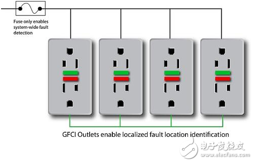
Example of GFCI socket for distributed fault identification
Localized overcurrent detection allows the system management controller to pinpoint the fault. This controller can decide whether to shut down only one module, or shut down most of the system, or shut down the entire system in the worst case. Because the maintenance personnel know the problem, rather than checking each subsystem one by one, this information enables faster commissioning and minimizes downtime. In addition, this allows a portion of the system to be shut down for maintenance while the remaining systems can continue to operate normally.
Figure 3
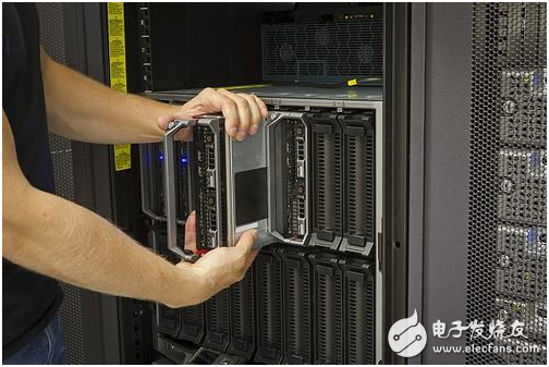
This picture shows that part of a blade server is being repaired while the system balance remains active.
Reduce the burden of event detection
A simplified overcurrent detection device such as the Texas Instruments INA300 can be used as a simple execution interrupt generator for the system management controller. This frees the system management controller from constantly polling the current levels of individual subsystems and making decisions based on polling results. This reduces the overall processing requirements for the system management controller, resulting in lower cost and power consumption.
to sum up
Distributed overcurrent detection provides system integrators with better system utilization and efficiency, faster and more accurate fault identification, and the ability to reduce the event detection burden of system controllers. In order to minimize the impact, the implementation is very simple, easy to manage, and requires minimal packaging. Miniaturization and simplified implementation are key to achieving multiple measurement points without increasing system complexity or making the system larger.
We will next introduce how jitter in the sample rate control signal reduces the SAR-ADC ENOB.
references
Ground Fault Circuit Breaker (GFCI), OSHA, US Department of Labor
Download INA300 data sheet
TI Overcurrent Detection Products - Prevent Overcurrent in Multiple Applications, 2014
About the author
Dan Harmon is the Sensing Business Development Manager for the TI Sensing Products Group. In his 29 years of service to TI, he has supported the development of a wide range of technologies and products, including interface products, imaging analog front ends (AFEs), and charge coupled device (CCD) sensors. He also serves as TI's USB-IF representative and chairman of the TI USB 3.0 Promotion Group. Dan earned a bachelor's degree in electrical engineering from Dayton University and a master's degree in electrical engineering from the University of Texas at Arlington.
The through-wall terminals can be installed side by side on panels with thicknesses ranging from 1mm to 10mm, and can automatically compensate and adjust the thickness of the panel to form a terminal block with any number of poles. In addition, isolation plates can be used to increase air gaps and creepage distances.
Through-Wall Terminal,Through Wall Terminal Block,Through-Wall Terminal Extender,Through-The-Wall Terminal Block
Sichuan Xinlian electronic science and technology Company , https://www.sztmlchs.com