
1. PTC effect A material has a PTC (Positive Temperature Coefficient) effect, that is, a positive temperature coefficient effect, which only means that the resistance of this material increases with increasing temperature. For example, most metal materials have a PTC effect. Among these materials, the PTC effect appears as a linear increase in resistance with increasing temperature, which is known as the linear PTC effect.
2. Nonlinear PTC effect The material undergoing phase change will exhibit a sharp increase in resistance along the narrow temperature range of several to ten orders of magnitude, namely the nonlinear PTC effect, as shown in Figure 1. A considerable number of types of conductive polymers exhibit this effect, such as polymeric PTC thermistors. These conductive polymers are very useful for making overcurrent protection devices.
3. KT series polymer PTC thermistor for overcurrent protection polymer PTC thermistor is often referred to as self-recovering fuse (hereinafter referred to as thermistor), due to its unique positive temperature coefficient resistance characteristics (ie The PTC characteristics, as shown in Figure 1, are therefore extremely suitable for use as overcurrent protection devices. The thermistor is used in the same way as a normal fuse, as shown in Figure 2.
Figure 1. Resistance-temperature curve of a PTC thermistor
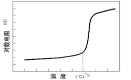
Figure 2. Circuit diagram of the use of polymer PTC thermistor 
When the circuit works normally, the thermistor temperature is close to room temperature and the resistance is very small. The series connection in the circuit does not hinder the current from passing through; and when the circuit has an overcurrent due to the fault, the thermistor increases the temperature due to the increase of the heating power. When the temperature exceeds the switching temperature (Ts, see Figure 1), the resistance becomes very large instantaneously, limiting the current in the circuit to a very low level. At this time, almost all of the voltage in the circuit is applied to both ends of the thermistor, so that it can protect other components. When the human is cut off the circuit to eliminate the fault, the resistance of the thermistor will quickly return to the original level. After the circuit is removed, the thermistor can be used without replacement. Figure 3 is a schematic diagram showing the change of current during the protection of the thermistor to the AC circuit. After the thermistor is activated, the current in the circuit is greatly reduced. In the figure, t is the operating time of the thermistor. Because the polymer PTC thermistor has good designability, it can adjust its sensitivity to temperature by changing its switching temperature (Ts), so it can play both over-temperature protection and over-current protection, such as KT16. The -1700DL specification thermistor is suitable for overcurrent and overtemperature protection of Li-Ion and NiMH batteries due to its low operating temperature.
Figure 3. Current changes in the circuit during the thermistor action 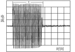
Effect of Ambient Temperature on Polymer PTC Thermistor Polymer PTC thermistor is a direct-heating, step-type thermistor whose resistance change process is related to its own heat and heat dissipation, so its current is maintained (Ihold ), the operating current (Itrip) and the operating time are affected by the ambient temperature. Figure 4 is a schematic diagram showing the relationship between the holding current, operating current and ambient temperature of a thermistor. When the ambient temperature and current are in zone A, the thermistor heating power is greater than the heat dissipation power and will act; when the ambient temperature and current are in zone B, the heating power is less than the heat dissipation power, and the thermistor will remain in the inactive state for a long time; When the current is in the C zone, the heat dissipation power of the thermistor is close to the heating power, and thus may or may not operate. Figure 5 is a schematic diagram showing the relationship between the operating time of the thermistor and the current and ambient temperature. When the thermistor has the same ambient temperature, the operating time is sharply shortened as the current increases. The thermistor has a shorter operating time and a smaller holding current and operating current when the ambient temperature is relatively high.
Figure 5. Thermistor action characteristic curve 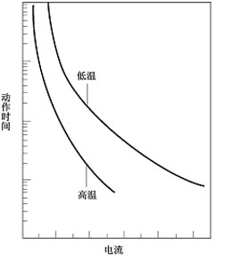
Figure 4 Maintain current, operating current and temperature 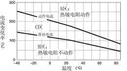
Recovery characteristics of the polymer PTC thermistor after operation The polymer PTC thermistor can be repeatedly used because it can be recovered due to resistance. Figure 6 is a schematic diagram showing the change of resistance with time during the recovery process after the thermistor is activated. The resistance is generally restored to a level of about 1.6 times the initial value in ten to several tens of seconds. At this time, the holding current of the thermistor has returned to the rated value and can be used again. In general, thermistors with smaller areas and thicknesses recover relatively quickly; while thermistors with larger areas and thicknesses recover relatively slowly. Figure 6. Recovery characteristic curve after the thermistor is activated 
Characteristics of KT Series Polymer PTC Thermistors Polymer PTC thermistors are conductive polymer materials with positive temperature coefficient characteristics. The most significant difference between them and conventional fuses is that the former can be reused many times. Both products provide overcurrent protection, but the same polymer PTC thermistor provides this protection multiple times, and the fuse must be replaced with another one after providing overcurrent protection.
The main difference between a polymer PTC thermistor and a bimetal circuit breaker is that the former does not reset until the accident is not eliminated, but the bimetal circuit breaker can reset itself when the accident still exists. This can result in electromagnetic waves and sparks at reset. At the same time, re-enabling the circuit in the event of a fault in the circuit can damage the device and is therefore unsafe. The polymer PTC thermistor can maintain a high resistance state until troubleshooting.
The difference between a polymer PTC thermistor and a ceramic PTC thermistor lies in the initial resistance of the component, the operating time (reaction time to an accident event), and the difference in size. Polymer PTC thermistors with the same holding current Compared with ceramic PTC thermistors, polymer PTC thermistors are smaller in size, lower in resistance, and faster in response.
DC Permanent Magnet Gear Motor
Dc Motor,24V Dc Gear Motor,Electric Gear Motor,Dc Permanent Magnet Gear Motor
NingBo BeiLun HengFeng Electromotor Manufacture Co.,Ltd. , https://www.hengfengmotor.com