
The main purpose of the amplifier circuit is to provide power to the load. The main features are as follows: First, the output power refers to the product of the alternating voltage and the alternating current, that is, the AC power; second, the AC power is at the input. It is defined as a sine wave and the output waveform is basically not distorted; the third is that the output power is large, so the energy consumed in the circuit and the energy supplied by the power supply are also large; the fourth is that the transistor often works in an extreme application state, thereby considering necessary Thermal measures and protection against overcurrent and overvoltage.
In all electronic audio-visual equipment, there is a problem with the optimal solution of the power output, that is, in order to obtain the maximum power output without increasing the investment of the circuit, this is the best combination of the power amplifier and the speaker system.
The purpose of the power amplifier combination is to obtain the maximum power output in order to achieve the minimum equipment investment. Take the complementary power amplifier circuit of Figure 1 as an example: and for the power amplifier, it works in the low-bias class A and B complementary states. Its output power is similar to the Class B state.
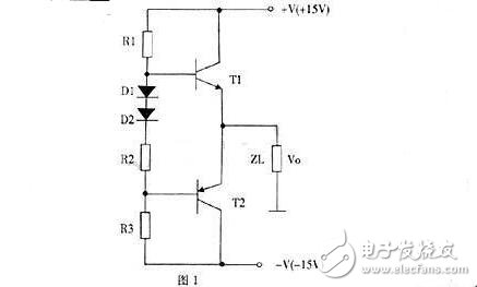
In order to achieve maximum output power, the size of the load should maximize the product of the current output and voltage output of the power tube. The state at this time is called the power matching state. In the speaker system of the audio equipment, the output impedance of the sound should be the total impedance of the combined state of the speaker, so that the output power of the sound is the rated standard power, otherwise the output power of the sound will not meet the requirements.
For example, if the audio standard connector is marked as 4Ω or 100W, then the impedance on the connector is the parallel connection of two 8Q speakers, and each speaker can get 50W, so the integrated speaker system is 4Ω, 100W, otherwise 100w power output cannot be achieved. .
Power amplifier protectionThe power tube is the most vulnerable device in the power amplifier circuit. Most of the damage is due to the actual dissipation power of the tube exceeding the rated value. In addition, if the power amplifier is mismatched with the speaker or the speaker is used for medium and long-term overload, it is also very easy to damage the speaker (or speaker). Therefore, in the audio equipment, the purpose of protection is to protect the expensive amplifier and speaker, so the power supply, amplifier, The overload and short circuit protection of the speakers is absolutely necessary.
(1) Power supply protection: Figure 2 is the discrete component voltage regulator circuit. In the circuit, Ri is the overload current sampling resistor. When the voltage is greater than 0.7V, V13 is turned on, the collector potential drops, the regulating tube V11 is disconnected, and the power supply is limited. Output current.
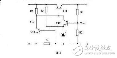
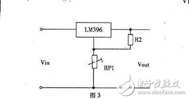
Figure 3 is a tunable output voltage module with a power consumption of 70W, a current of 10A, a voltage regulation of 20.8%, an output voltage of 1.25 to 15V, and short-circuit protection.
When using a switching power supply (such as chip CWl225), there is a special protection control terminal pin 10, as long as the input of over current or over voltage signal, you can achieve the purpose of protection.
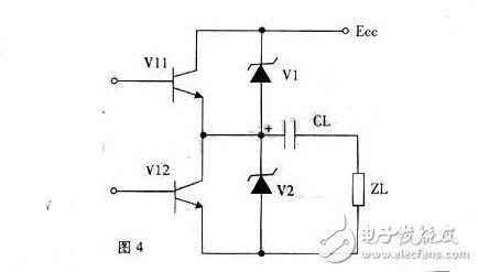
(2) Power amplifier-level transistor protection: In addition to the ambient temperature and the selection of a suitable heat sink, the power amplifier transistor mainly considers overcurrent and overvoltage protection. Currently, the integrated circuits used have current-limiting protection and heat. Cut off the protection function (such as HAl350, HA2211, LM2879, etc.), so pay attention to overvoltage protection when making the power amplifier, as shown in Figure 4. Relying on the internal breakdown of R (internal power supply) and Vl, V2, the overvoltage can not be raised to protect Vl, V2.
(3) Speaker speaker system protection: The protection of the sound system has two meanings: one is the overload of the audio speaker; the other is not the excessive audio power, but the offset of the DC potential, resulting in OCL without capacitive isolation. The BTL circuit speaker burned out. When overloading, the power amplifier circuit has been protected without additional consideration. Only the DC offset combined audio protection circuit is introduced here.
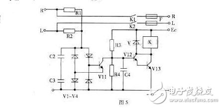
Figure 5 is a combined acoustic protection circuit. It can be seen from the figure that when the sound signals sent to the speakers by the left and right channels are bypassed by the capacitors C2 and C3 through R1 and R2 without DC offset, the rectifier bridge has no DC output, and V11 is cut off, V12 and V13. Conduction, relay K pull-in, left and right audio signals output through fuse F; when there is DC offset, the rectifier bridge output makes V11 turn on, V12, V13 cut off, relay K release cut off the audio signal to protect the speaker.
In the circuit, C2 and C3 are filter capacitors. When C4 has the switch, the function of delaying the speaker is turned on to avoid the impact noise when starting up. V has the function of short-circuiting K and the anti-electromotive force to protect the V12 and V13 transistors.
The understanding or evaluation of the power amplifier circuit is mainly considered from the three aspects of output power, efficiency and distortion .
1. In order to obtain the required output power, the circuit must select a triode with a sufficiently large collector power consumption, and the working current and collector voltage of the power amplifier tube are also high. In circuit design, the first thing to consider is how to fully exert the triode function without damaging the triode. Since the working state of the power amplifier tube in the circuit is often close to the limit value, the power amplifier current should be carefully adjusted and used, and it should not be used excessively.
2. From the aspect of energy consumption, the power output of the power amplifier is ultimately provided by the power supply. For example, the power consumption of the power amplifier in the radio should account for 2/3 of the whole machine, so it is necessary to pay great attention to improve the circuit efficiency, that is, the output power and the power consumption. ratio.
3. The input signal of the power amplifier circuit has been amplified several times, and has sufficient strength, which will greatly move the working point of the power amplifier tube, so the power amplifier circuit is required to have a large dynamic range. The working point of the power amplifier tube is not properly selected, and the output will be seriously distorted.
Use of power amplifiers:The power amplifier dominates to some extent whether the entire system can provide good sound quality output.
For many people, the amplifier is not very well understood. It is not clear which accessories are needed in the amp speaker to play the amp effect to an optimal state. The first one is to install a resistor under the speaker to do current sampling. In fact, the feedback is still the voltage signal. It is the analog current feedback. It is the most people, but this circuit is defective. There are two reasons:
1. His output gain will change with impedance. As a result, it is not constant voltage applied to the end of the horn 2, as if the power applied to the horn is constant. Since the sound pressure characteristic curve of the speaker is tested under the constant voltage output, the simple circuit is not good, the listening is not good, and it is fun, but there is an improved circuit, mainly based on voltage negative feedback. A proper amount of this type of current negative feedback can make a good sound, but the effect of current negative feedback is to change the damping coefficient of the power amplifier, which has little effect on the amplitude-frequency characteristics.
2. The sampling point is below the speaker. The speaker is an inductor. The current flows through the inductor and its phase changes. The low frequency is good. The high frequency can be shifted by 90 degrees, and the phase characteristics are extremely poor. The second type: negative-resistance amplifier, except for some special occasions, the first one to be used for sound and the success is YAMAHA, its main function is to improve the low-frequency extension, but for 200Hz or more. The frequency will degrade the sound quality, so it is generally used on ultra-low frequency active speakers. In fact, this circuit is used in conjunction with the speaker, and there is no practical use of it alone. The working principle is: If the speaker is a rigid body, then add a tube, it can become an ideal Holmo resonance box, then regardless of the size of the box, the thickness of the tube, as long as it meets the Holmó resonance Calculate the formula. Even the 20Hz resonance point can be done. The size of the box is only high efficiency. Because there are speakers on the speaker, the speaker is moving when the sound is sounding. The speaker is not a rigid body, then the box will not be produced. Hallo nostalgic.
Therefore, if the horn of the horn is stationary when it is sounding. Then, the box is close to the rigid body, and it can satisfy the conditions of Holmó resonance, and the resonance point of the box can be arbitrarily designed. When the sound is made, the work of letting the speaker not move is the task of negative resistance power amplifier. The working principle of the negative-resistance power amplifier is that when the horn is working in the low frequency band, its impedance characteristic changes abruptly. The amplifying circuit takes out the change and feeds it back to the power amplifier through current sampling, so that the power amplifier controls the horn in the form of current. The equivalent analysis of the circuit shows that the internal resistance of the amplifier is negatively calculated. During dynamic amplification, the internal resistance of the horn plus amplifier is close to zero. As a result, this circuit allows the horn to be strongly damped no matter which direction it is facing. As soon as the sound is over, the horn will not move, and the box will become rigid.
The third type: current mode feedback amplifier circuit, this is a practical current amplifier circuit, which is also true current type negative feedback. The feedback signal is current, not voltage, that is, it is not added at the negative feedback end, but is added. There is a current flowing in. This type of circuit was first used in video transmission, or in instrumentation like an oscilloscope.
Because of the low-resistance and negative-current feedback input, the high-frequency characteristics of this circuit are excellent, and the capacitive load has a strong driving capability. As long as it has been improved, it is found to be a good power amplifier, which can make up for some congenital deficiency of the voltage amplifier. Low open-loop frequency response, closed-loop transient frequency response distortion, and extremely weak capacitive load drive capability. The disadvantage is that the open-loop gain of this circuit is relatively low, and the distortion after the closed loop is an order of magnitude higher than that of the voltage amplifier. However, the total distortion done will not exceed 0.01%.
Power amplifiers are referred to as power amplifiers. For their main purposes, power amplifiers can be divided into two main categories, namely dedicated power amplifiers and civilian power amplifiers. In the stadiums, theaters, dance halls, conference halls, sound reinforcement in public places, and recording monitors, etc., there are often some unique requirements on their technical parameters. These amplifiers are often called special purpose. Amplifier or professional amplifier.
Hi-Fi music for home use, AV system playback, and karaoke entertainment amplifiers, often referred to as civilian amplifiers or home amplifiers. Although special amplifiers and civil amplifiers differ in some characteristic parameters, it is difficult to say that there is a clear boundary. For example, the amplifier used for music recording monitoring is probably one that can be used for home Hi-Fi or even Hi-end amplifiers. .
Hi-Fi amplifier and AV amplifier:
Hi-Fi amplifiers and AV amplifiers are the two main categories in home amplifiers. These two types of amplifiers are used for different purposes, and the design is not the same. Hi-Fi amplifiers are used to enjoy music, and users are pursuing as much "original" as possible. The users of AV amplifiers are pursuing the "live" effect that matches the picture, and even the exaggerated "live" effect. These two types of power amplifiers are not very good to directly compare the advantages and disadvantages. For example, the Hi-Fi power amplifier and the AV power amplifier with the price of more than 3,000 yuan, the cost of the Hi-Fi power amplifier is only on two channels, and the AV power amplifier Cost investment must take into account 5-6 channels, but also have a certain effect processing function. If you only look at the input of the two main channels, it is definitely lower than the input of the two channels of the Hi-Fi amplifier. The difference in its playback effect is obvious. But whether it is Hi-Fi amplifier or AV amplifier, there are high-end boutique and value-for-money.
In general, it is difficult to have an AV amplifier that can be fully compatible with Hi-Fi and AV. AV amplifiers and Hi-Fi music enjoyment are conditional. This condition is the requirement and standard when users enjoy music. The user is only used to enjoy some casual music, or only want to be able to hear the melody of the music, AV amplifier is relatively easy to satisfy, but if there is a high demand for music appreciation, the general AV amplifier is difficult to meet.
Transistor Amplifiers and Tube Amplifiers:
Amplifiers for Hi-Fi viewing can be divided into two types: transistor amplifiers and tube amplifiers. Hi-Fi amplifiers with integrated circuits or module circuits have been used before, but they are rare. There are no advantages and disadvantages between the transistor and the tube amps in the audio technology super forum, except that the applied devices are different (one is the transistor, the other is the electron tube). Because of the different types of devices, the physical and circuit characteristics are different. .
The current of the electron tube is formed by the attraction of electrons in the vacuum by the electric field force. The current of the transistor is formed by the transfer of the outer electrons of the semiconductor element under the action of the electric field force. This difference in physical basis causes the circuit characteristics to differ in practical applications. Relatively speaking, the working voltage of the tube power amplifier is higher, but the working current is relatively small, and the operating voltage of the transistor power amplifier is lower, and the working current is relatively large. There is a certain difference between the amps of the tube amp and the transistor amp, and the response of the two to the transient signal is also different. This difference has been adapted to different categories of music and different music viewers, so the combination of transistor amplifier and tube amp is formed in the Hi-Fi amplifier. However, in terms of brand, model, and quantity, the share of transistor amplifiers is still absolutely greater than that of tube amps.
Class A power amplifiers and Class B power amplifiers:
The working state of the transistor amplifier output stage transistor can be divided into Class A and Class B. The so-called Class A is simply to make the output stage transistors operate in the linear region during the positive and negative half cycles of the sinusoidal AC signal, while Class B is only to make the transistors of the output stage in the positive half cycle (or negative half cycle of the sinusoidal AC signal). ) works in a linear area. Due to the different operating states of the output stage transistors, the power utilization efficiency of the output stage (ie, the ratio of the output power amplifier to the power consumption) is also different. In a practical output circuit, the efficiency of class B is 2-3 times higher than that of class A.
Class A power amplifiers do not have crossover distortion, and the internal resistance of the output stage crystal is constant regardless of the actual output power. Class B power amplifiers always have a certain crossover distortion (although this distortion may be extremely small). In addition, the internal resistance of the output stage transistor is small at large output, but the internal resistance of the output stage transistor is relatively large at small output. . These differences make the sense of hearing different. The sound of the Class A amplifier is softer than that of the Class B amplifier. In addition, the low frequency control of the speaker is stronger than that of the Class B amplifier, especially at low volume. These characteristics of Class A power amplifiers make Class A power amplifiers do not require a large output power margin in practical applications. A 20W-30W Class A power amplifier has been able to push most of the speakers very well.
As mentioned above, the power efficiency of Class A power amplifiers is low, which causes a large amount of heat to be emitted when Class A power amplifiers work. In order to make the operating temperature of the transistor not exceed a certain limit, a heat sink of a large volume and area is required, which makes the volume and weight of the class A power amplifier relatively large.
Pure post-amplifiers and mono amplifiers:
Common amplifiers use a preamplifier (preamplifier) ​​and a power amplifier (rear stage) that amplify small signals in a single chassis. These amplifiers are often referred to as "combined amplifiers". The integrated amplifiers are easy to use and have Better performance and price ratio. However, this combined amplifier has some inherent shortcomings, and the most difficult one to overcome is the mutual interference between the pre-stage and the post-stage. In order to solve this problem, the pre-stage and the post-stage are respectively made in two casings, so that there is a pure post-stage power amplifier. Most of the pure final stage power amplifiers are two-channel structure, but this kind of structure makes the two channels interfere with each other and is not very easy to solve. In order to solve the interference between the two channels, two A mono pure final stage amplifier with separate channels.
Separating the power amplifiers one by one, the main meaning is to improve the quality of the amplifier, rather than pursuing this form. If they are only separated from each other in form, although the mutual interference problem can be solved, but other parameters are not significantly improved, then this separation is limited to improve the overall quality of the power amplifier. The power amplifier has a transistor and a tube, and the front stage also has a transistor and a tube. For audio enthusiasts and music lovers, there are a variety of combinations in the pre-stage and post-stage, and different combinations have different sound effects, which makes the user have more choices.
The front stage mated with the pure final stage power amplifier has a great influence on the quality of the whole sound system. First of all, it must have certain qualities. Otherwise, the advantages of pure post-level or mono can't be exerted. It is even possible to highlight the "bad" of a poor pre-level, and the overall sound effect is even worse. Moreover, different pre-stages and post-stages have different timbre characteristics, and users can select different combinations according to personal preference. For example, many audio and music enthusiasts like to use the combination of “pre-biliary and post-stone†(ie, the pre-tube front stage and the post-transistor stage). It is felt that this combination not only plays a large role in the power output of the transistor, but also has a good transient response. Features, but also appreciate the sweet and mellow "feel" of the pre-stage sound of the tube, but this combination is not a "golden rule", because the specific pre- and post-level have their own characteristics, and the preference for the tone is due to people. Different, users can find out their favorite combination according to the specific situation.
How much output power should the Hi-Fi amplifier have:
The output power of Hi-Fi power amplifiers is affected by many factors. Firstly, this output power has a great relationship with the connected speakers. Secondly, it is related to the power quality of the power amplifier. Then there is the environment used, that is, the room. The volume of space is related.
The speaker has a parameter called sensitivity, and its unit is dB/m? W, the meaning is the sound pressure (dB) generated when the speaker gets 1W of electric power from the speaker 1m. If the sensitivity of a certain speaker is 90dB, then a sound pressure of 90dB at 1m requires 1W of power to push. To get 100dB of sound pressure, you need 10W of power to push it. But if the sensitivity of the speaker is 80dB (such as ATC's SCM-10), to achieve 100dB sound pressure, 100W of power is needed to drive. Most speakers have a sensitivity of about 85dB-90dB. For these speakers, 10W-30W undistorted power can already have enough sound pressure.
The quality of the power amplifier itself has a great relationship with the output power that the power amplifier should have. One of the parameters of the power amplifier is called the damping coefficient, which is a parameter indicating the ability to control the speaker, but this parameter has a moderate range and is directly related to the specific speaker. In general, if the quality of a power amplifier is good, its performance parameters can be maintained at a certain level at 30 W output. Then there is no need to ask the amplifier to have a larger power output. However, if the quality of the power amplifier is not ideal, when the output power increases, it will cause deterioration of its performance parameters, then the output power of the power amplifier should have a certain margin to ensure that there are still some good parameters under the practical output power. . Under normal circumstances, when the power amplifier is a class A output or a tube power amplifier, there is no need to have excessive output power margin, and the output power of 20W-30W is sufficient. However, if it is a Class B power amplifier or a poor quality power amplifier, then the power output of the power amplifier should have a large margin. In addition, if the mated speakers are large-inverted, the amplifier should also have a large output power margin. When considering the output power of the power amplifier from the quality of the power amplifier itself, selecting the power margin to a larger size can actually improve the adaptation of the power amplifier and the speaker.
The main significance of selecting a power amplifier with a large output power is not because it requires such a large sound pressure, but to improve the adaptation state of the power amplifier to the speaker. If a power amplifier with a moderate output power is already able to control the speaker, then there is no need to put higher output power requirements on the amplifier. The use environment, that is, the space volume of the room has a certain relationship with the power that the power amplifier should output. The output power mentioned above is based on the space volume of the room below 40. If the space of the room is large, then The output power of the amplifier should be increased.
Features of the tube amplifier output stage:
The power output stage of the tube power amplifier has three circuit types, one is a push-pull output circuit with an output transformer. This type of output circuit accounts for the vast majority of tube amps. In the output transformer of the push-pull circuit, the DC component is small, and the second harmonic distortion is also small. The output power of such a circuit can be made relatively large, so the applicable range is relatively large. Generally speaking, audio enthusiasts who are interested in the sound of the amplifier are suitable for this type of output stage. However, the design and process of the output transformer of this type of power amplifier is very important. If there are deficiencies in the design and process of the output transformer, the frequency response and transient response of such a power amplifier are often not ideal. In addition, due to the constraints of the output transformer, the adaptation range of the mating speaker is small.
Another type of power output stage circuit type is a single-ended class A circuit. This type of circuit also has a transformer, but the output transformer of this type of circuit has a large DC component, and the requirements for the output transformer are higher than those of the push-pull output circuit. In addition, the requirements for the power supply are also relatively high. This type of output circuit is characterized by a relatively large number of second harmonic components. Although this is a kind of harmonic distortion, for the music signal, the second harmonic is a highly harmonious sound, so it sounds very good. This feature makes the function of this output circuit very special in the sound of the sound, especially when the power amplifier stage uses a triode, the human voice sounds very sweet, and the string music in the chamber music sounds very delicate, or, The sound of this type of amplifier is very flavorful. However, the output power of such amplifiers is not easy to make, so if the speakers used are less sensitive, they are more reluctant when delivering large orchestral music. This type of tube amp is very popular with some audio players. It is often equipped with a high-power transistor amplifier, and there is also one such amplifier. It is meant to complement each other in the tone, but this also shows that this type of amplifier The timbre characteristics are indeed touching.
There is also a type of tube amplifier output stage circuit is an OTL circuit, the so-called OTL circuit is no output transformer circuit. Modern transistor amplifier output stages are almost entirely improved versions of OTL circuits or OTL circuits. The characteristic parameters of the tube and the transistor are different from the working state. The transistor amplifier is easy to adapt to the speaker with the impedance of 4-8, and the tube amp needs to be replaced by the output transformer to adapt to the 4-8 speaker. Since the electronic tube OTL power amplifier has removed the output transformer, it has greatly improved the technical parameters compared with the two types of circuits mentioned above. The power amplifier sound of this type of output circuit is very characteristic, compared with the previous two types of output circuits. With magnificent momentum and wide sound field, its sound is warmer and more delicate than transistor amplifiers. These amplifiers can accommodate a wide range of speaker impedances because they do not have an output transformer. However, such output stage power amplifiers have low efficiency, and the design, process, and debugging are relatively complicated. The power amplifiers of such output circuits are only found in some high-end models, and it is difficult to see low-cost popular models.
Current characteristics:
The understanding or evaluation of the power amplifier circuit is mainly considered from the three aspects of output power, efficiency and distortion.
1. In order to obtain the required output power, the circuit must select a triode with a sufficiently large collector power consumption, and the working current and collector voltage of the power amplifier tube are also high. In circuit design, the first thing to consider is how to fully exert the triode function without damaging the triode. Since the working state of the power amplifier tube in the circuit is often close to the limit value, the power amplifier current should be carefully adjusted and used, and it should not be used excessively.
2. From the aspect of energy consumption, the power output of the power amplifier is ultimately provided by the power supply. For example, the power consumption of the power amplifier in the radio should account for 2/3 of the whole machine, so it is necessary to pay great attention to improve the circuit efficiency, that is, the output power and the power consumption. ratio.
3. The input signal of the power amplifier circuit has been amplified several times, and has sufficient strength, which will greatly move the working point of the power amplifier tube, so the power amplifier circuit is required to have a large dynamic range. The working point of the power amplifier tube is not properly selected, and the output will be seriously distorted.
we are professional disposable vape manufacturer from shenzhen china and can offer one stop oem& odm vape service. Disposable vape pen,disposable electronic cigarette,vape pen,disposable ecigs,ecigs pen,e-cigs pen,vape pod,ELFBAR disposable vape pen is portable and fashion disposable electronic cigarette, disposable ecigs pen are trending featured vape pen for vapors as it's safety and easy to use. Disposable vape pod,disposable vape, wholesale vape,vape wholesale,vape pen manufacturer and supplier.disposable vape pen,disposable electronic cigarette,disposable ecigs pen,disposable ecigs stick,disposable e-cigs pen,disposable vape factory,disposable vape pod,disposable vape device,vape pen,vape stick, vape wholesale,wholesale vape,customized dispsoable vape pen,customized vape pen,OEM&ODM disposable ecigs pen,disposable electronic cigarette wholesale, wholesale disposable electronic cigarette,distribute vape pen,vape pen distribute,high quality vape pen,high quality vape pod.
elf bar disposable vape pen,Disposable vape pen,disposable electronic cigarette,vape pen,disposable ecigs,ecigs pen,e-cigs pen,vape pod
Shenzhen Onlyrelx Technology Co.,Ltd , https://www.onlyrelxtech.com