
First, PLC programming language
1. Ladder programming language
The ladder diagram follows the form of the relay control circuit. It simplifies the symbol evolution based on the commonly used relay and contactor logic control in the electrical control system. It is visual, intuitive and practical.
The design of the ladder diagram should pay attention to the following three points:
(1) Ladder diagrams are arranged in order from left to right and top to bottom. Each logical line starts at the left bus, then the strings of the contacts, and is coupled, and finally the coil is connected to the right bus.
(2) Each step in the ladder diagram is not a physical current, but a “concept currentâ€. From left to right, there is no power supply at both ends. This "concept current" is only a graphical representation of the conditions under which the coil should be turned on during the execution of the user program.
(3) The input relay is used to receive external input signals, but cannot be driven by the contacts of other relays inside the PLC. Therefore, only the contacts of the input relay appear in the ladder diagram without its coil. The output relay outputs the program execution result to the external output device. When the output relay coil in the ladder diagram is powered, there is a signal output, but it is not directly driven by the output device, but can be realized by a relay, transistor or thyristor of the output interface. The contacts of the output relay are available for internal programming.
2. Statement table programming language
The instruction statement represents a mnemonic programming method similar to computer assembly language, but is easier to understand than assembly language. An instruction statement consists of three parts: the step sequence, the instruction word and the action device number.
3. Control system flow chart programming diagram
The control system flow chart is a relatively new programming method. It expresses a control process with a functional diagram like the control system flow chart, and the International Electrotechnical Commission (IEC) is currently implementing the development of this new programming standard.
Second, the basic instructions
The basic instructions are shown in the table.
Instruction fetch
LD
I, Q, M, SM, T, C, V, S, L
Normally open contact logic operation start
Negative instruction
LDN
I, Q, M, SM, T, C, V, S, L
Normally closed contact logic operation start
Coil drive command
Q, M, SM, T, C, V, S, L
Drive coil output and command
I, Q, M, SM, T, C, V, S, L
Serial connection of a single normally open contact
And non-instructions
AN
I, Q, M, SM, T, C, V, S, L
Serial connection of a single normally closed contact
Or instruction
I, Q, M, SM, T, C, V, S, L
Parallel connection of a single normally open contact
Or non-instruction
ON
I, Q, M, SM, T, C, V, S, L
Parallel connection of a single normally closed contact
Set instruction
I, Q, M, SM, T, C, V, S, L
Keep the action
Reset instruction
I, Q, M, SM, T, C, V, S, L
Keep reset
Positive jump
ED
I, Q, M, SM, T, C, V, S, L
Pulse output on the rising edge of the input signal
Negative jump
EU
I, Q, M, SM, T, C, V, S, L
Pulse output at the falling edge of the input signal
Null operation instruction
NOP no
Third, make the steps empty
1, standard contacts LD, A, O, LDN, AN, ON,
LD, fetch instructions. Indicates a normally open contact command connected to the input bus, that is, the start of the normally open contact logic operation.
LDN, reverse instruction. Indicates a normally closed contact command connected to the input bus, that is, the start of the normally closed contact logic operation.
A, with instructions. Used for series connection of a single normally open contact. AN, with non-instructions. Used for series connection of a single normally closed contact.
O, or instruction. Used for parallel connection of a single normally open contact. ON, or non-instruction. Used in parallel for a single normally closed contact.
2, positive and negative transition ED, EU
ED, after detecting a positive transition (from OFF to ON), the enable flow is turned on for one scan cycle.
EU, after detecting a negative transition (from ON to OFF), the enable flow is turned on for one scan cycle.
3, output =
=, the specified parameter bit in the image register is turned on when the output instruction is executed.
4, set and reset instructions S, R
S. When the set (set) instruction is executed, N points from the address parameter specified by bit or OUT are set.
R, when the reset (set to 0) instruction is executed, N points from the address parameter specified by bit or OUT are reset.
The number of points set and reset can be 1-255. When the reset command is used, if the bit or OUT specifies T or C, the timer or counter is reset and the current value will be cleared.
5, the empty operation command NOP
The NOP instruction does not affect the execution of the program, and the number of executions is N (1-255).
Fourth, programmable controller ladder design rules
1. Contact arrangement
The contacts of the ladder diagram should be drawn on a horizontal line and not on a vertical branch.
2. Serial and parallel processing
When several series circuits are connected in parallel, the series circuit with the most contacts should be placed at the top of the ladder diagram. When several parallel circuits are connected in series, the parallel circuit with the most contacts should be placed on the leftmost side of the ladder diagram.
3. Coil arrangement
The contact cannot be drawn to the right of the coil and the coil can only be connected to the right of the contact.
4. No double coil output
If the coil of the same component is used two or more times in the same program, it is called a double coil output. At this time, the previous output is invalid, and only the last time is valid, so the double coil output should not appear.
5. Reprogramming the circuit
If the circuit structure is more complicated, it is easier to re-use some contacts to draw its equivalent circuit and then program it.
6. Programming
For complex programs, the program can be divided into several simple blocks. Each segment starts from the leftmost contact, is programmed from top to bottom, and then connects the program piece by piece. 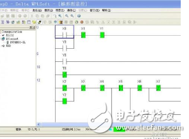
We provide many kinds of phenolic diaphragm to meet the different needs of different customersthey are widely used in Hi-Fi speakers,professional audio,horn speakers,car speakers and other high-end products.
We are experienced in manufacturing and have strong capability.
Our products are popular in many countries and areas.
We have professional acoustical testing systems and instruments.
We promise to offer you highest quality and best service!
Phenolic Diaphragms,Phenolic Replacement Diaphragm,Replacement Phenolic Diaphragm,Diaphragm Phenolic Voice Coil,Phenolic diaphragm driver unit
Taixing Minsheng Electronic Co.,Ltd. , https://www.ms-speakers.com