
Experimental circuit 1: single tube light control test (street light automatic control principle)
Required components: 1 photoresistor (5mm diameter, 2kΩ brightness resistance), 1 1/4W2kΩ resistor, 1 9014 triode, 1 high-brightness LED, 2 5th battery case, 37mm× 1 piece of 25mm universal printing board.
Learning steps:
1 Use a multimeter × 1K file to measure the resistance of the photoresistor, and the resistance is small when illuminated. Light does not follow the resistance.
2 Analyze the principle of the light control circuit.
3 Install the wiring.
4 Turn on the power test: When the light is shining, the light-emitting tube is not bright, and the photosensitive resistor is held by hand to block the light, and the light-emitting tube is bright, indicating success.
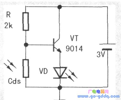
Circuit principle: As shown in the figure below, transistors C and E are connected in series with LEDs and connected to a 3V battery. The size of the resistance between transistors C and E depends on Ub. (Determined by the voltage divided by the Cds photoresistor). The 2kQ resistor is connected in series with the Cds photoresistor and then connected to the 3V power supply. When there is light (daytime), the resistance of the photoresistor Cds becomes smaller (the voltage distribution in the series circuit is proportional to the resistance value), and the distributed voltage is reduced. Ube drops, the resistance of transistors C and E becomes larger, and the current through the arc tube decreases (the reason why the daylight does not light). Otherwise (the dark) lights up.
Experimental circuit 2: optical control switch experimental circuit
Required components: vTl9014, VT2910, a total of 2 transistors, 1 R1 photoresistor, 1 RP10kΩ resistor, 1 R24-7kΩ resistor, 1 VD LED, 1 special printed board, 1 battery case.
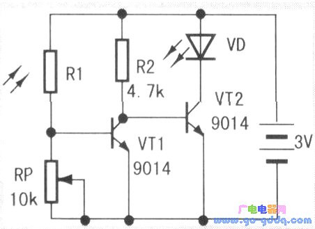
Circuit principle: As shown in the figure below, the photoresistor R1 and the adjustable resistor RP form a series circuit. When the light is dimmed, the resistance of the photoresistor increases, and the voltage across the RP decreases, causing the resistance between the VT1 transistors C and E to change. Large, leading to VT2, Ub. When the voltage between C and E rises, the resistance decreases rapidly and the LED is turned on. The opposite is not bright. Electronic light control switch, the light tube is connected to the relay, can control various electrical equipment, can be used as a robot light control probe.
Installation sequence: first install R2, R1, then install RP adjustable resistor, two triodes and LED.
After power up, adjusting the RP can change the control requirements.
Nanning Ousibang Information Technology Co., Ltd. , https://www.ousibangvape.com