
LabVIEW is a graphical programming language introduced by National Instruments (NI). It is also a well-known virtual instrument development platform. It plays a leading role in the key concept of "software as instrument". It combines the high performance and flexibility of graphical programming with high-end performance and configuration features designed for test and measurement and automation control applications, providing the necessary data acquisition, instrument control, measurement analysis and data display applications. Development tools. LabVIEW's presentation and functionality are similar to actual instruments, but LabVIEW programs make it easy to change settings and functionality. Therefore, LabVIEW is especially useful in laboratories and where it is necessary to change the parameters and functions of the instrument and equipment frequently. This design is based on the LabVIEW platform environment to build a virtual multimeter. The knob of the virtual multimeter is designed according to the actual DT9205 mode.
The data acquisition card is used to input external signals into the computer, and various parameters are measured in the software interface of the virtual multimeter.
2. Virtual multimeter design 2.1 Display panel designUse the [Control / New / Value / Turntable] command to place a turntable control on the front panel and set its properties: set the data type to [Unsigned Long]; [On the Text Label] tab, double-click [Text Label] For the column option, write the name corresponding to the knob, and then click the [Insert] button, repeat it multiple times, and write the name of each item. The knob interface is shown in Figure 1.
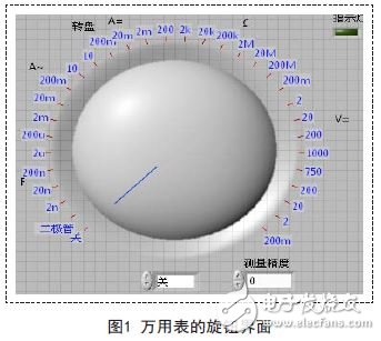
Place a string on the front panel to display the measurement results. Place a numerical input control to control the measurement accuracy. The user can select the measurement accuracy through the keyboard input or drop-down menu. At the same time, a work indicator light is placed to indicate the working state of the instrument. Place a text display box to display time and information.
2.2 Software Design of Virtual MultimeterIn the rear panel, a conditional structure is placed to instruct the multimeter to perform different actions on different scales of the knob. Set 32 ​​branches in the conditional structure, so that each branch performs 32 different actions, and connects the knob to the [branch selector] of the conditional structure. The 0-31 branch corresponds to the text label value of the knob.
Branch 0 shows the system's open and close status. The default is off, the indicator is off, and the display shows [Off].
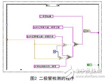
Branch 1 is responsible for detecting the diode. When the red test lead is connected to the diode anode, the circuit in the system is turned on, indicating “The red test lead is connected to the diode anodeâ€. When it is reversed, it will display “The red pen is connected to the diode cathodeâ€. When the test leads are not connected to the diode, "No diodes are detected" is displayed. The block diagram is shown in Figure 2.
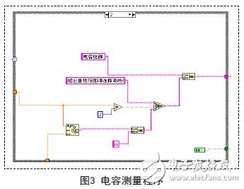
Branches 2 through 6 are responsible for the detection of the capacitance, and each branch has a different range. In the measurement, the size of the data is first detected to determine whether the measured value exceeds the range. If the range is not exceeded, the measurement accuracy is read next; if the range is exceeded, “Exceeding the measurement range, please select the high-end position†is displayed in the text box, prompting the user to convert the high-end position.
The block diagram is shown in Figure 3.
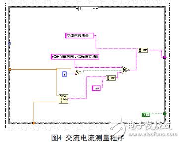
Branches 7 through 10 are responsible for AC current measurements, and branches 11 through 14 are responsible for measuring DC current. The measurement principle is the same and the range is different. When measuring the software design, first determine the size of the measured value, and then select the corresponding precision display. The block diagram is shown in Figure 4.
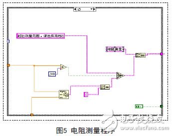
Branches 15 through 21 are responsible for resistance measurements. The range of the resistance range is quite wide. The multimeter can measure correctly within the range. If the measurement range is exceeded, the front panel will display “Exceeding the measurement range, please select the high-end positionâ€.
The block diagram is shown in Figure 5.
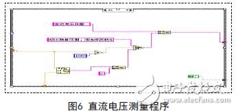
Branches 22 through 31 are responsible for voltage measurements. The measurement branch design is the same as the various design methods described above, with only units and sizes. The block diagram is shown in Figure 6.
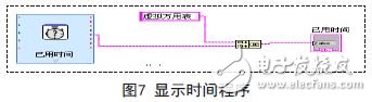
Set a time-generating function, then use a string concatenation control to connect the information to be displayed with the time string. The block diagram is shown in Figure 7.
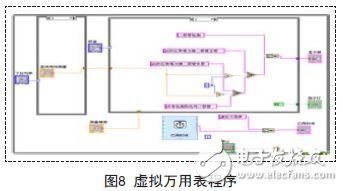
After the programming is complete, you must also add a loop program to make the multimeter work continuously. Use the While loop to control the operation of the program. The entire block diagram is shown in Figure 8. At this point, the design of the virtual multimeter is completed.
Experiments are a bridge between theory and practice. In recent years, traditional laboratories have many limitations, such as outdated experimental equipment, slow update speed, high cost, etc., which are increasingly unable to meet the needs of teaching and research.
With the rapid development of virtual simulation technology and network technology, building network virtual labs and virtual instruments will become the economic and efficient preferred solution.
Portable power system ,Portable power storage,Portable solar system, Outdoor power station, Portable power station
SHENZHEN CHONDEKUAI TECHNOLOGY CO.LTD , https://www.szfourinone.com