
The intelligent alarm system makes full use of the existing telephone network for design, and uses the telephone keyboard operation circuit, the ringing identification circuit, the remote message circuit, the automatic identification of the main called off hook circuit, the dual tone dialing (self ringing) circuit, etc., to solve the alarm. Not timely, false negatives, false positives, etc., and can improve the call completion rate. It is mainly used for burglar alarms in homes, shops, offices, and places with valuables.
This article refers to the address: http://
1 overall design
1.1 Technical requirements
After investigation and research, it is technically and carefully analyzed that it is necessary to meet the following six technical requirements in order to achieve the two main objectives of perfect function and convenient operation.
(1) The sensitivity of the alarm is high, and it is required to prevent false alarms;
(2) The spatial distance between the accident location (alarm station) and the called object (receiving station) should be unlimited;
(3) voice and digital information are transmitted on the same channel;
(4) Due to different user environments, the types and quantities of sensors used are also different;
(5) using E2PRoM curing program;
(6) If it crashes due to any reason, it should be able to resume operation normally. According to the above requirements, a system block diagram as shown in FIG. 1 is constructed.
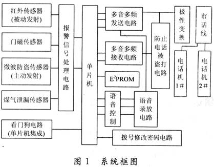
1.2 Main functions of the system
(1) When there is an alarm in the room (such as someone illegally entering the room, gas leak, fire, etc.), the smart phone alarm system can know the alarm through various sensors in time, judge the type of the police, and immediately automatically Dial the preset 2 phone numbers in sequence. After dialing, first determine whether the other party picks up the phone, and if so, play the corresponding recorded voice alarm content according to different alarm conditions; otherwise, after the hook is on, dial a set of preset calls until all the two phones are connected.
(2) The built-in telephone dialing system of the alarm device can send voice or digital alarm information of the location, user name, telephone number and other information of the accident to the two telephones designated by the user, so that the alarm can be processed in time. The two telephone types include mobile phones, pagers, and home phones. You can enter 2 reduced instructions and user information through the dial of the telephone, just as simple as operating the calculator. Thanks to the digital recording technology, the user can record the voice by himself, repeatedly record and play, and store and play in two segments. It has two states: out-of-way arming, staying in and out, and it is suitable for both the home and the unmanned.
(3) After the power is cut off, the backup battery of this alarm is automatically activated immediately.
(4) When the phone is stolen, it can be alerted in time.
2 Technical measures
(1) The public telephone line is used as the information transmission medium, and the wireless method is not used.
(2) Transmission of alarm information by voice mode or digital information mode, can be heard on the telephone, easy to use.
(3) The alarm device is provided with a circuit for modifying the user's password. The password of the telephone alarm device in the home can be modified through a telephone line at a remote location. The remote control alarm is fortified or disarmed.
(4) Install the watchdog circuit, and it can resume normal operation after the crash.
(5) Write two reduced instructions in the E2PROM, which can be permanently saved after power off.
3 smart phone alarm hardware design
The hardware part of the smart phone alarm is composed of a dialing circuit, an automatic pick-up circuit, a signal sound detecting circuit, a voice recording and reproducing circuit, an alarm circuit and a watchdog circuit.
3.1 Main circuit design
3.1.1 Dialing circuit
The dialing circuit uses the HT9170 and HT9200A as dual-tone multi-frequency (DTMF) signal receivers and generators, respectively. The automatic dialing chip adopts the serial DTMF dialing chip HT9200A, receives the telephone number sent by the CPU and sends a dual tone multi-frequency signal to the telephone line to establish a connection between the calling party and the called user. Each output frequency of the HT9200A is determined by a combination of different bit codes of 5 bits (D4 to D0). When the chip select signal CE is low, the CPU serially inputs 5-bit code to the data input terminal DATA of the HT9200A through the P0.5 port, latches the data on the falling edge of CLK, and transmits the signal from the output terminal DTMF through the analog switch. The line carries the dial signal of the DTMF tone.
3.1.2 Signal Generator HT9200A
The HT9200A is a serial DTMF signal generator with good temperature adaptability and an operating temperature range of -20 to +70 °C in an 8-pin DIP or SOP package.
3.1.3 Signal Receiver HT9170
The HT9170 integrates a digital decoder and a dual-tone DTMF receiver with filter function to operate in power-down mode and suppression mode. The HT9170 uses a digital calculation method to identify 16 times of DTMF audio decoded into a 4-bit code output. The high-precision conversion capacitor filter separates the audio DTMF signal into a low-frequency signal and a high-frequency signal, and the self-contained dialing audio blocking circuit can eliminate the blocking circuit required by the pre-filter.
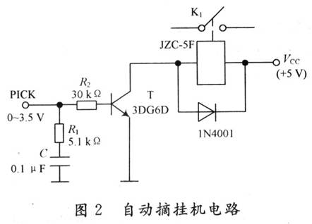
3.1.4 Automatic pick-up machine circuit
The automatic pick-up circuit is shown in Figure 2. It consists of a triode inverting amplifier circuit and a relay. The system detects the signal level from 0 to 3.5 V. When the system detects the alarm signal, the main control system makes PICK high level, the triode is turned on, the relay is closed, K1 is turned on, and the system automatically picks up the machine. After the user completes the command operation (such as after the external alarm process is completed), the main control system gives PICK a low level, the triode is turned off, the relay is released, the switch K1 is disconnected, and the machine is automatically hung up.
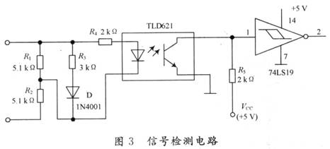
3.1.5 signal sound detection circuit
The dialing tone of the telephone system, the ringing tone and the busy tone have an average frequency of 450 Hz (±25 Hz), but the discontinuous ratio is different, and there is a significant difference in time (the dial tone is 450±25 Hz continuous signal, the busy tone is 0.35). s pass, 0.35 s off, ringback tone is 1 s pass, 4 s off). Therefore, the signal tone is an analog signal. The signal tone detection circuit needs to complete the analog to digital conversion. The signal detection circuit is shown in Figure 3. The photocoupler is used to detect the signal, the resistors R1 and R2 are used for voltage division, and R3 and D are used for shunting. The parameters of each component are shown in the figure. The signal is outputted by the optocoupler and the negative pulse signal is output. The output is processed by the inverter 74LS19 with Schmitt trigger, and converted into a digital signal for the main control system to count.
The counting time is 5 s, the lower limit of the dial tone is (450-25) × 5 = 2 125, and the upper limit of counting is (450 + 25) × 5 = 2 375, that is, the counting range is 2 125 to 2 375. Similarly, the busy tone count range is 1 041 to 1 212, the ring back tone count range is 425 to 475, and the no tone sound count should be 0. Therefore, the system uses the intermediate value of the adjacent counting limits of different tones to distinguish different tones.
3.2 voice recording and playback circuit
The system's voice recording and playback circuit selects the single-chip voice recording and playback circuit series integrated circuit ISD1420, ISD1420 is the product launched by American ISD company, the single-chip recording and playback time is 8~20 s, and the sound quality is good. The ISD1420 uses CMOS technology and includes an oscillator, mic preamp, automatic gain control, anti-aliasing filter, smoothing filter, speaker driver and E2PROM array. The smallest recording and playback system requires only a microphone, a speaker, two buttons, a power supply, and a small number of resistors and capacitors. After the recording and playback operation is finished, the device automatically enters the low-power power-saving mode and consumes only 0.5μW.
The playback process of the circuit is made by the P1~P7 ports of the AT89C51 of the single-chip microcomputer to the PLAYL port of the ISD1420, and the trigger circuit is played; when a low level is given, the playback is stopped.
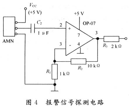
3.3 Alarm signal detection circuit
The alarm signal detection circuit is shown in Figure 4. This system uses AMN pyroelectric infrared sensor for detection. Use the better performance OP-07 to amplify the signal, use a single power supply, the amplification factor is set to 10 (Au=R2/R1=10). When someone enters its detection range, the sensor's No. 2 pin outputs the forward level. After being amplified, an alarm start signal is generated and sent to the main control circuit.
4 software design of smart phone alarm
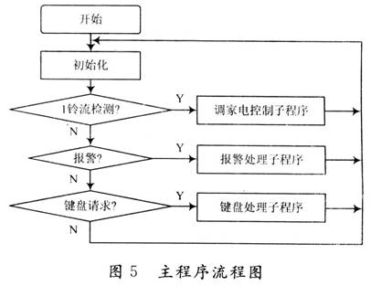
The software part mainly through assembly language programming, control the high and low potential of P0, P1, P2, P3 port of single chip AT89C51 to achieve the alarm purpose. First, the MCU is initialized. The P3.2 port of the AT89C51 of the single-chip microcomputer starts to detect the alarm signal. When the P3.2 port detects a high level, it indicates that there is an alarm signal input. At this time, the P0.0 port gives a high level signal to make the system The automatic pick-up circuit automatically picks up the machine, and the dialing circuit is also in the dialing state. If the T0 port count result of the MCU is allowed to dial, P2 outputs a set of level signals so that the dialing circuit automatically dials 110 alarm, otherwise it hangs up. When the dialing is successful, the P1.7 port of the MCU gives a high level signal, triggering the playback circuit to automatically play the alarm content pre-stored in the ISD1420. After the alarm is over, the P0.0 port of the MCU gives a low level signal, and the system automatically hangs up to complete the entire alarm process. The software flow is shown in Figure 5.
5 Conclusion
After installation and commissioning, the phone automatic alarm implements the following functions:
(1) The system is connected in parallel with the telephone, and only occupies the telephone line during the alarm. After the alarm is over, the system is separated from the telephone line, which does not affect the normal use of the telephone. The public communication network is used as the transmission medium, as long as the user of the telephone is installed. This alarm can be installed.
(2) The alarm has the characteristics of automatic, fast and accurate. When the alarm occurs, it can automatically dial 110, and the other party automatically plays the recorded voice alarm content after picking up the phone. If the other party is busy, it can automatically pick up the hook and automatically cycle in the order of dialing, detecting and playback.
(3) Most of the traditional alarm systems have the problem of simultaneous alarm channel. Due to the use of the public communication network, this alarm has been successfully solved, which will not cause confusion and ensure reliable alarm.
(4) Low cost, can be widely used in the security of warehouses, stores, and homes.
Servo Actuator,Long Linear Actuator,Mini Electric Linear Actuator,Mechanical Linear Actuator
Kunshan Zeitech Mechanical & Electrical Technology Co., Ltd , https://www.zeithe.com