
1. Logic programming
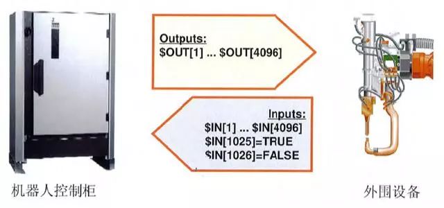
The input and output settings are for the communication between the robot and peripheral devices, such as tool sensors, etc.
2. Available logic instructions
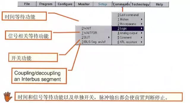
3. Waiting time function logic instruction
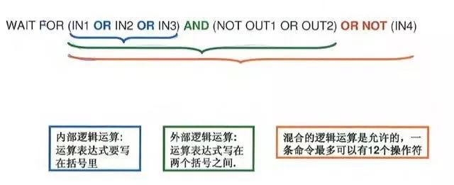
(2) The waiting signal program can be written, such as the following common forms.
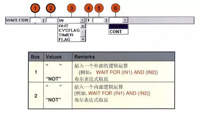
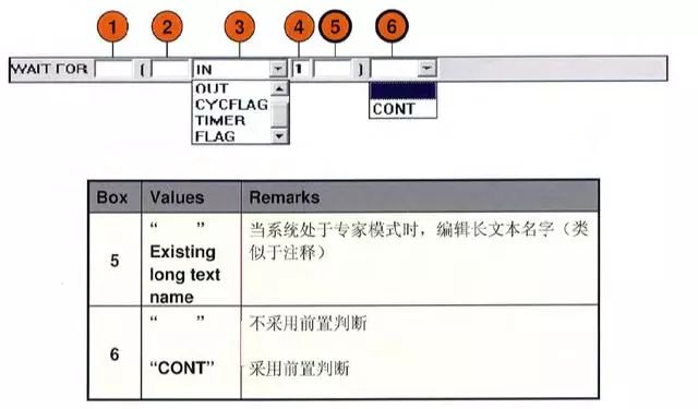
(3) If the "WAIT FOR" command is selected, the following parameters can be set
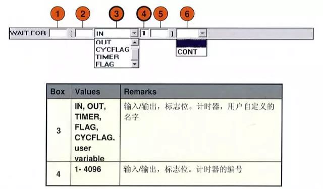
(4) If the "WAIT FOR" command is selected, your following parameters can be set
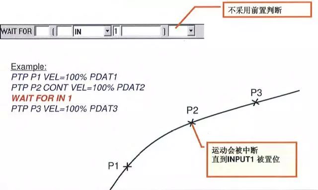
(5) If the "WAIT FOR" instruction is used to interrupt the pre-judgment form, every point will be accurately reached even if the condition has been met.
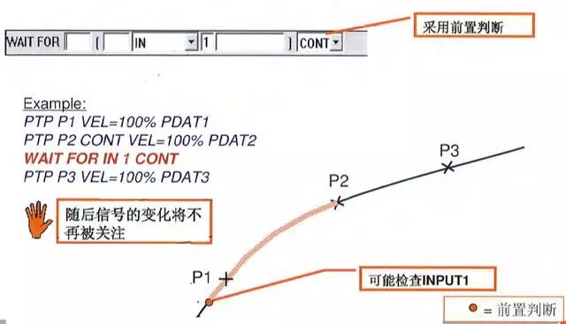
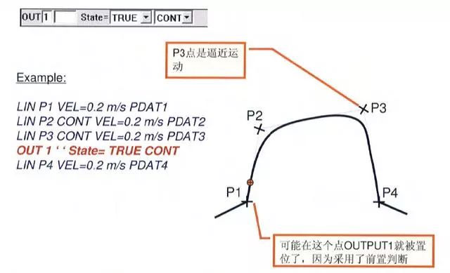
(6) If the "WAIT FOR" instruction selects the CONT mode, your conditions will be pre-judged, and if the conditions are met, then the approximation method will be adopted.
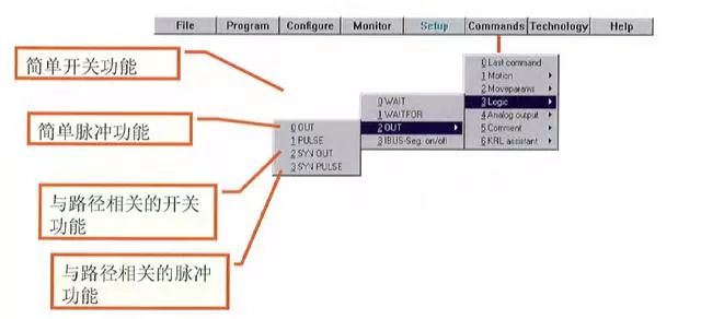
5. Output function
(1) The following functions can be selected by option
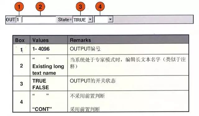
(2) Simple output instruction one
If the "OUT" command is selected, then the following parameters can be set
(3) Simple output instruction two

4) Simple output instruction three
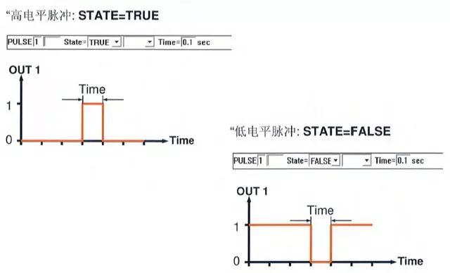
(5) Simple pulse command one
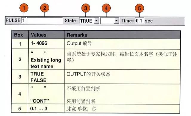
(6) Simple pulse command two
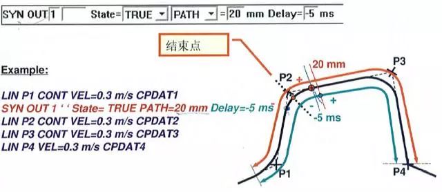
6. Synchronous output instructions
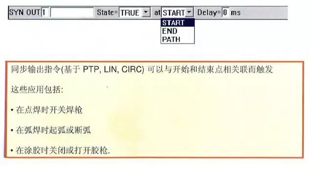
7. Signal output
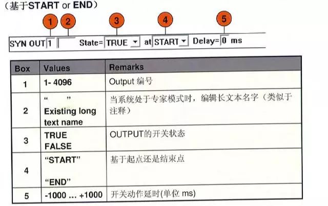
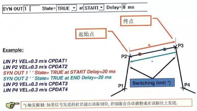
(1) Output a signal at the beginning or end of the path
If the "OUT" command is selected, then the following parameters can be set
(2) Both the start point and the end point are accurately reached
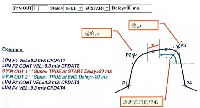
(3) The starting point is accurate to the point, and the end point is the approach point
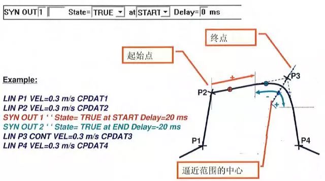
(4) Both the starting point and the ending point are approaching the point
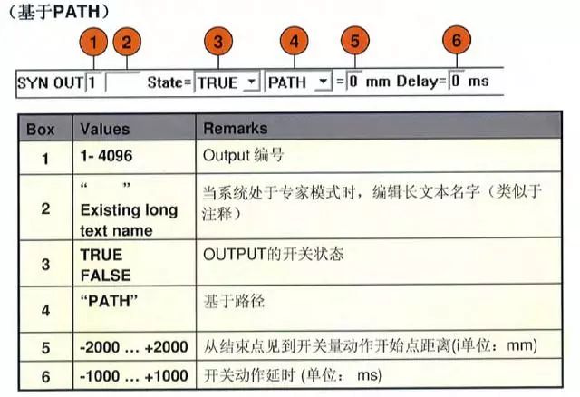
(5) Where to output the signal in the path
a. If you use the path-related SYNOUT-PATH command, you can follow the path of the program
Know the distance at any point to trigger the switch.
b. Like the synchronization instructions related to the start and end points, this instruction can also be sent in advance or delay
signal.
c. Path-related switch control is only allowed to be used in continuous path motion (LIN or C
IRC).
d. The SYNOUT-PATH instruction is for the next motion instruction.
e. If a SYNOUT-PATH command is applied to a PTP movement, it will be
The software refuses.
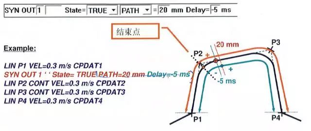
(6) Path related synchronous output instruction one
If the "OUT" command is selected, then the following parameters can be set
(7) Path related synchronous output instruction 2
The starting point is the exact arrival point, and the end point is the approach point
(8) Path-related synchronous output instruction three
The start and end points are both approach points
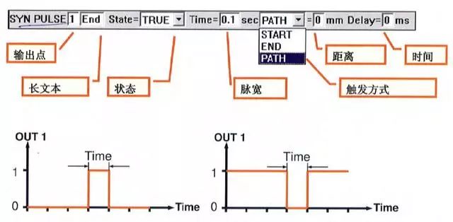
8. Synchronous pulse command
If "SYN PULSE" is selected, then the following parameters can be set
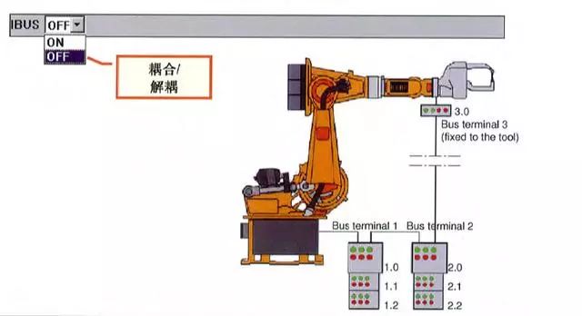
9. Partial coupling and decoupling of Inter bus
If "IBUS-seg.on/off" is selected, then the following parameters can be set
Shenzhen Wanheyun Computer Co.,Ltd. , https://www.xcypc.com