1 Introduction to the algorithm
1.1 H.264 coding model framework
H.264 is widely welcomed by the industry for its high compression ratio, high image quality and good network affinity. Under the same quality conditions, the data compression ratio of H.264 is 2 to 3 times higher than that of MPEG-2, and 1.5 to 2 times higher than that of MPEG-4. It requires only 50% of MPEG-4 and 12.5% ​​of MPEG-2.
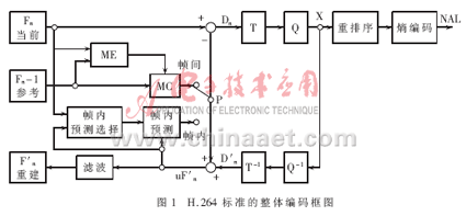
The H.264 standard adopts a layered architecture. The system is divided into: Video Coding Layer (VCL), which is responsible for efficient digital video compression, and Network Abstraction Layer (NAL), which is responsible for packaging and transmitting data. H.264 encoded images are generally classified into three types: I frames, P frames, and B frames. An I frame is an intra coded frame whose encoding does not depend on the encoded image data. The P frame is a forward predicted frame, and the B frame is a bidirectional predicted frame, and the motion estimation is performed according to the reference frame when encoding. At the same time, H.264 has done a lot of work to improve the fault tolerance of image transmission, and redefines the structure division suitable for images. At the time of encoding, each part of the image frame is divided into a plurality of Slice structures, and each slice can be independently encoded without being affected by other parts. Slice consists of the most basic structure of the image, macroblocks, each macroblock containing a 16x16 luma block and two 8x8 chroma blocks. The overall coding block diagram of the H.264 standard is shown in Figure 1. In the encoding process, after the original data enters the encoder, when intra-coding is adopted, the corresponding intra prediction mode is first selected for intra prediction, and then the difference between the actual value and the predicted value is transformed, quantized and encoded. After the encoded code stream is subjected to inverse quantization and inverse transform, the prediction residual image is reconstructed, and then the reconstructed frame is obtained by adding the predicted value, and the obtained result is smoothed by the deblocking filter and then sent to the frame memory. When inter-coding is used, the input image block is first motion-estimated in the reference frame to obtain a motion vector. The residual image after motion estimation is integer-transformed, quantized, and encoded, and then transmitted to the channel along with the motion vector. At the same time, another code stream is reconstructed in the same manner, and then deblock filtered to be sent to the frame memory as a reference image for the next frame encoding.
This article refers to the address: http://
1.2 H.264 key technology
1.2.1 Intra Prediction H.264 introduces intra prediction to improve compression efficiency. Intra prediction coding uses the neighboring pixel values ​​to predict the current pixel value and then encodes the prediction error. This prediction is block based. For the luminance component, the block size can be selected between 16×16 and 4×4, 16×16 has 4 prediction modes, 4×4 has 9 prediction modes; for chrominance components, the prediction is for the entire 8×8 There are 4 prediction modes for the block.
1.2.2 Inter Prediction <br> The size of the block used for inter prediction is variable. Assuming a block-based motion model, all the pixels in the block do the same translation. Outside the edge of the moving object or the moving object, this assumption will be larger than the actual input, resulting in a large prediction error. Reducing the size of the block allows the hypothesis to remain true in the small block. In addition, the blockiness caused by small blocks is relatively small, so small blocks can improve the prediction effect. H.264 uses a total of 7 ways to divide a macroblock. In each mode, the size and shape of the block are different. The encoder can select the best prediction mode according to the content of the image. Using blocks of different sizes and shapes can save the code rate by more than 15% compared to predictions using only 16x16 blocks.
At the same time, intra prediction uses finer prediction accuracy, and the motion vector of the luminance component in H.264 uses 1/4 pixel precision. The motion vector of the chroma component uses 1/8 pixel precision.
1.2.3 Multi-frame reference H.264 supports multi-frame reference prediction. Up to 5 decoded frames before the current frame can be used as reference frames to generate predictions for the current frame, improving the error recovery capability of the H.264 decoder.
1.2.4 Integer transform H.264 is a 4×4 integer transform technique for residual images, which uses fixed-point operations instead of floating-point operations in previous DCT transforms. In order to reduce the coding time, it is also more suitable for the transplantation of hardware platforms.
1.2.5 Entropy coding H.264 supports two entropy coding methods, namely CAVLC (Context-Based Adaptive Variable Length Coding) and CABAC (Context-Based Adaptive Arithmetic Coding). Among them, CAVLC has higher anti-error ability, but the coding efficiency is lower than CABAC; while CABAC has high coding efficiency, but the calculation amount and storage capacity are larger.
1.2.6 deblocking filtering
The function of deblocking filtering is to eliminate the blockiness caused by the prediction error in the reconstructed image after inverse quantization and inverse transform, thereby improving the subjective quality and prediction error of the image. The filtered image will be placed in the buffer for inter prediction as needed, rather than just improving the subjective quality, so the filter is located in the decoding loop. For intra prediction, an unfiltered reconstructed image is used.
2 algorithm implementation
2.1 Platform selection
2.1.1 ADSP-BF561 chip introduction ADSP-BF561 is a high-performance fixed-point DSP video processing chip in the Blackfin series. It has a clock speed of up to 750 MHz and the core contains two 16-bit multiplier MACs, two 40-bit accumulator ALUs, four 8-bit video ALUs, and a 40-bit shifter. The two Data Address Generators (DAGs) in the chip provide addresses for simultaneous access to dual operands from memory and can handle 1 200 megabits of multiply-accumulate operations per second. The chip has dedicated video signal processing instructions and 100KB of on-chip L1 memory (16 KB instruction cache, 16 KB instruction SRAM, 64 KB data cache/SRAM, 4 KB temporary data SRAM), 128 KB on-chip L2 memory SRAM with dynamic power management. In addition, Blackfin processor also includes a wealth of peripheral interfaces, including EBIU interface (four 128 MB SDRAM interface, four 1 MB asynchronous memory interface), three timers/counters, one UART, one SPI interface, and two Synchronous serial interface and 1 parallel peripheral interface (supporting ITU-656 data format). The Blackfin processor is structurally exemplified by support for media applications, especially video applications.
2.1.2 ADSP-561 EZkite
The ADSP-BF561 video encoder platform uses the Analog Devices ADSP-BF561 EZ-kit Lite evaluation board. The evaluation board includes an ADSP-BF561 processor, 32 MB SDRAM and 4 MB Flash. The AD-V1836 audio codec in the board can be connected to an external 4-input/6-output audio interface. The ADV7183 video decoder and ADV7171 video encoder An external 3 input / 3 output video interface can be connected. In addition, the EV kit includes a UART interface, a USB debug interface, and a JTAG debug interface. The analog video signal input by the camera is converted into a digital signal by the video chip ADV7183A. This signal is compressed from the API-BF561 PPI1 (parallel external interface) into the ADSP-BF561 chip, and the compressed code stream is converted from ADSP-BF561 by ADV7179. PPI2 port output. This system can load programs through Flash and supports serial and network transmission. The original image, reference frame, and the like in the encoding process can be stored in the SDRAM.
2.2 Algorithm selection and optimization scheme
2.2.1 Algorithm selection
There are more than one source code for H.264 implementation, the most common of which are JM, X264 and T264. Compared to the three implementation source code, X264 is more efficient than T264. Moreover, compared with the widely used JM coding model, X264 greatly improves the coding speed while taking into account the coding quality, so X264 is selected as the algorithm prototype.
2.2.2 Optimization scheme <br> The optimization scheme optimizes the algorithm from three levels: algorithm level, code level, platform level. The specific optimization method is described below.
2.2.2.1 Selection of specific parameters of the encoder<br> The encoder uses the main level. The quantized values ​​of the I, B, and P frames are 26, 31, and 29, respectively, and the flow control parameters are selected as CBR. The IDR frame interval is set to 50, and the B frame interval is 2 frames. This choice is to take a compromise between speed and amount of calculation. Select B frame and increase its quantization value, which can increase the compression ratio by about 10% compared with the baseline grade and IPPP structure. The calculation of the B frame, because it does not need to be a reference frame, there is no need to perform deblocking filtering and interpolation calculation. Under the qp of 31, many blocks will be judged as skip mode coding, so the majority of the B frame total operation amount will be reversed. Lower than P frames.
2.2.2.2 Algorithm level optimization <br> Algorithm level optimization mainly refers to the replacement or optimization of some algorithms in the case of parameter selection. As with the choice of parameters, algorithm level optimization is also mainly guided by the optimization strategy. For example, the motion matching criterion is to use SSD, SAD or SATD. If you only look at the accuracy, choose SSD best; if you only look at the running speed, choose SAD is the best; if you want to balance the two, then the choice of SATD is a better solution. One problem that should be paid attention to when optimizing the algorithm is to consider the support of the actual running platform. For example, in the strategy of pursuing speed, the matching criterion selects SAD, and if only half of the points are calculated, the calculation speed is greatly reduced. However, if you consider the design of the ADSP-BF561 assembly instructions, you will find that doing so will increase the number of instructions, which will make the speed lower. Algorithm level optimization includes the following parts:
(1) Divide the remainder. The improvement strategy is that the floating-point algorithm should be changed to integer as much as possible, 64 bits should be changed to 32 bits as much as possible, and 32 bits should be changed to 16 bits as much as possible. For some calculations, it is changed to look up the table. On the ADSP-BF561 platform, a 32-bit integer division takes 300 CYCLEs, and a look-up table requires only a few CYCLEs. This improvement can significantly increase the speed.
(2) Saturation function. In the calculation of video, almost every pixel calculation will call the saturation function. In the implementation of X264 code, this part of the code has been changed to look-up table function. In other codec implementations, this part is also changed to a judgment and The form of several logical operations. For most DSP platforms, using the judgment jump will interrupt the pipeline. Even if the platform has a better jump prediction function, interrupting the flow will still cause stall. So the lookup method is an efficient method. In the ADSP-BF561 assembly instruction, saturation can be performed by setting the instruction suffix or using some special instructions. Even without looking up the table, using different saturation algorithms in different situations can greatly improve the efficiency of code execution.
(3) MC part function. In the actual measurement, it is found that the MC part function is not as efficient as the MC part of the ffmpeg decoder, so this part of the code is replaced with the corresponding part in ffmpeg. In addition, the qpel16_hv function has redundancy in the calculation, and reducing these redundancy can improve the efficiency of the code.
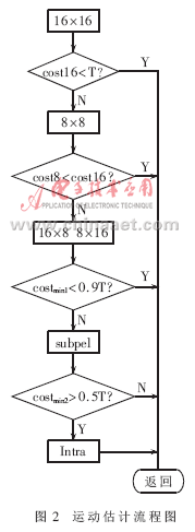
(4) Algorithm substitution and improvement. Improvements in interframe prediction: The improvement of the algorithm mainly focuses on the improvement of me (motion estimation), and the flow is shown in Figure 2. Costmin1=min(cost16, cost8, cost16×8, cost8×16), costmin2=min(costmin1, costsub), in order of integer pixel positions of 16×16, 8×8, 16×8 and 8×16 macroblocks To make predictions, perform sub-pixel estimation and intra prediction, and select the matching criterion function (using sad as the matching criterion function) to obtain the minimum mode for encoding. Each time a pattern is calculated, the sad value is compared to an empirical threshold. When the sad value is less than this threshold, the motion estimation is ended immediately, thereby reducing the amount of computation.
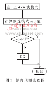
Improvements in intra prediction: The intra prediction mode adopted by the H.264 standard has directionality in addition to the DC mode, and adjacent 4×4 blocks have correlation. According to such correlation, only the prediction mode and its adjacent two prediction modes are selected as the prediction mode of the current 4×4 block on the upper and left sides of the current 4×4 block, and when the thresholds are greater than an empirical threshold, Only use DC mode. Such a scheme does not need to calculate nine prediction modes one by one, and takes a compromise in complexity, coding efficiency, quality, and speed. The process is shown in Figure 3.
2.2.2.3 Code Level Optimization <br> For the ADSP-BF561 platform, the code level optimization work includes the following aspects:
(1) Inline function. Change the function of the function body that is frequently called to be inline. There are options for inline function optimization in the compilation conditions. The use of inline functions is a compromise between code size and operational efficiency. Depending on the actual situation, the size of the code is not a constraint, so you should use as many inline functions as possible. Select the when declared inline option in the project configuration.
(2) Jump prediction. The ADSP-BF561 uses static prediction to predict conditional judgments. Unsuccessful predictions can cause delays of 4 to 8 core clocks (CCLK). If you know the probability of some jumps in advance, put the most probable branch first, you can reduce the stall caused by the unsuccessful prediction.
(3) Use hardware support loops. For most platforms, it is also possible to increase the efficiency by deploying a small loop of loops. The ADSP-BF561 has two sets of hardware counters to support the loop. Therefore, unless it is a loop of more than three layers, unrolling the loop body does not improve efficiency.
(4) Memory. The memory of an embedded system is an invaluable resource. Avoid frequent dynamic application and release of memory, which can reduce fragmentation and improve memory utilization. The X264 project also does not frequently request to release memory. In the project, the specific approach is to write platform-related malloc and free functions. The intermediate data that is frequently used is allocated in the L1 data space.
(5) The comment does not require a code. Remove the unnecessary parts of the code, mainly remove the CAVLC and some parts of the code rate control, csp, cpu, information statistics, debugging and psnr calculations, in order to reduce the file size and remove some of the jumps in the code. turn. It is not recommended to remove the code. You can use annotations or use macro switching to prevent unused code from being used in future parameter changes.
2.2.2.4 Platform Level Optimization The corresponding programming reference and hardware reference of ADSP-BF561 are described in detail. Some of the platform's own optimization features, such as CACHE opening and configuration, are not specifically discussed here.
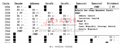
(1) Assembly code writing There are two methods for using assembly optimization: for the LEAF function (the rest of the function is no longer called in the function body), the whole function is completely rewritten by the assembly instruction; for the NONLEAF function, the asm keyword can be used. , embed assembly code in C code. In the process of writing assembly code, some situations will cause the pipeline to be stalled. Pay special attention to avoid these situations when writing assembly code. The IDE integrates the PIPLELINE VIEWER tool, as shown in Figure 4. After writing the assembly code, you can use it to observe the runtime pipeline. If there is a stall, etc., the reason will be given, and the optimizer will change the code according to the tool analysis result to improve the execution efficiency.
The IDE from ADI has a very flexible setup that generates code for different restrictions based on user needs. If the memory is limited, the user can set the code to generate smaller files; if the user pays more attention to the running speed, set the compiler to generate faster code, or take a compromise between them.
The ADSP-BF561 is specially designed to process video-related DSP commands (video pixel operations, vector operations, etc.). These dedicated instructions support certain special operations (additive, multi-parameters, and average) through SIMD technology or operating specialized hardware. Addition and subtraction, etc.) to increase the speed of operation. As in the case of the SAD case, the instruction in the assembly instruction specifically calculates the sum of the absolute values ​​of the difference between the consecutive 4 pixels and the other 4 consecutive pixels, and the result is added to the value of the accumulator. If you want to calculate the interval (that is, take half of the point calculation), you need to downsample the data after adding the instruction, which is time consuming and inaccurate. So the strategy of calculating half of the pixel is not applicable to the ADSP-BF561. These specialized instructions are not used in the code automatically generated by the compiler. Therefore, the algorithm can only be optimized and optimized according to the understanding of the algorithm and the familiarity with the platform.
When writing assembly code, you should also pay attention to the use of some registers, such as I0, I1, whose value is not only used as an address index, but also affects the calculation results of many instructions. When using these registers, be sure to push them to the appropriate values. In addition, regarding the loading of data, the alignment principle should generally be followed, but such requirements are often not met when doing motion estimation to calculate the matching criterion function. Therefore, if you can separate the two to calculate, it will be more efficient.
In addition, the use of registers should be used as reasonably as possible, and the use of parallel instructions can also improve the efficiency of code execution.
(2) Hierarchical Memory Structure The ADSP-BF561 processor uses an improved Harvard architecture and hierarchical memory structure. The Level 1 (L1) memory runs at full speed with very little delay. At the L1 level, the instruction memory stores instructions. Two data memories store data, and a dedicated temporary data memory stores stack and local variable information. A module consisting of multiple L1 memories for a mix of SRAM and CACHE. The Memory Management Unit (MMU) provides memory protection to protect system registers from accidental access to independent tasks running on the core. L1 memory is the highest performing and most important memory in the ADSP-BF561 processor core. Off-chip memory can be extended by SDRAM, FLASH, and SRAM through the External Bus Interface Unit (EBIU) to access up to 132 MB of physical memory. According to this feature, placing code with higher execution rate into the L1 instruction cache enables the code to run faster. The IDE provides a Profile tool that counts the number of CYCLEs and the percentage of total CYCLEs for each function at runtime. By putting more time-consuming part of the algorithm code in X264, such as the mode selection part code into the L1 instruction space, the operation efficiency can be further improved. The Profile tool statistics result is also the basis for selecting the assembly optimization function. The IDE can optimize the code based on the profile results. The X264 code Profile statistics have a lot to do with the test data. Using data more similar to the future application site as the test data can make the statistical results closer to the future application environment. In order to achieve more accurate statistical results, it is best to perform statistics in the Simulation phase. Although this is very time consuming, it is worthwhile to get an accurate statistic as a reference. In addition, the CACHE VIEWER tool can provide runtime CACHE usage, and use it to analyze the use of CACHE, which is useful for improving the efficiency of code running.
3 Evaluation of experimental results
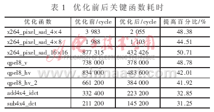
3.1 Key Function Optimization Test Results <br> The above optimization method is used to optimize the coding key functions. The time consumption of the optimized functions before and after is shown in Table 1. It can be seen that the above optimization method can greatly reduce the coding time.
3.2 Test Sequence Test Results <br> The frame rate test before and after optimization of the three test sequences at the bus frequency of 120 MHz is shown in Table 2. As can be seen from Table 2, the above optimization method can significantly increase the frame rate.

3.3 Test results at different data bus frequencies <br> For different bus frequencies, the optimized encoding frame rate is different. The results are shown in Table 3. The test sequence used is foreman.

This paper introduces the framework of H.264 standard, studies the implementation scheme of X264 software, analyzes the architecture of ADSP-BF561 processor, and proposes a set of X264 optimization schemes, including: algorithm substitution and improvement, inline function, assembly code. Writing, high speed memory applications, etc. The test results show that the optimized algorithm has significantly improved coding efficiency and has strong practical value. However, this paper mainly optimizes the encoder from the aspects of coding speed and efficiency. In the complexity and coding quality, it is still necessary to continuously analyze and integrate the key algorithms and propose a new optimization algorithm. At the same time, the code rate control of the encoder has not been perfected. How to effectively control the rate control under the premise of reducing the computational complexity requires further study.
references
[1] Bi Houjie. A new generation of video compression coding standards - H.264. Beijing: People's Posts and Telecommunications Press, 2005.
[2] Magic Liu Feng. Video Image Coding Technology and International Standards. Beijing: Beijing University of Posts and Telecommunications Press, 2005.
[3] Li Yushan. Digital Visual Video Technology. Xi'an: Xi'an University of Electronic Science and Technology Press, 2006.
[4] MICHAELURAPIS A, STTHRING K, SULLIVAN GH264/MPEG-4 AVC reference software manual.Joint Video Team
(JVT) of ISO/IEC MPEG&ITU-T VCEG (ISO/IEC JTC1/SC29/WG11 and ITU-T SG16Q.6) 14th Meeting, Hong Kong, PRC China 17-21, 2005.
Capacitive Type Oil Detector,Oil Contamination Detector on the Piping Line,Oil Detector
Taizhou Jiabo Instrument Technology Co., Ltd. , https://www.taizhoujiabo.com
