
How to understand the power circuit diagram A circuit diagram usually has dozens or even hundreds of components, their lines cross and cross, the form is very varied, beginners often do not know where to start, how to read it. In fact, the electronic circuit itself has a strong regularity, no matter how complicated the circuit is, it can be found through analysis that it is composed of a few unit circuits. The more complicated circuit, after analysis, can be found that it is also composed of a few unit circuits. Therefore, beginners only need to familiarize themselves with the basic unit circuits that are commonly used, and then learn to analyze and decompose the power of the circuit. It is not difficult to understand the general circuit diagram.
According to the function of the unit circuit, they can be divided into several categories, each type has many kinds, and there are probably hundreds of all unit circuits. Below we select the most commonly used basic unit circuit to introduce. Let's start with the power circuit.
First, the function and composition of the power circuit
Each electronic device has a power supply circuit that supplies energy. The power circuit has three kinds of rectifier power supply, inverter power supply and frequency converter. Most of the common household appliances use DC power. The easiest way to power a DC power supply is to use a battery. However, the battery has the disadvantages of high cost, large volume, and need to be replaced from time to time (the battery needs to be charged frequently), so the most economical and convenient and convenient is to use a rectified power supply.
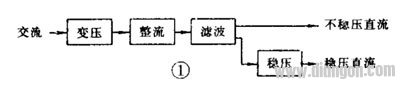
The power supply in the electronic circuit is generally low-voltage direct current, so if you want to convert from 220 volts to DC, you should first convert 220 volts AC into low-voltage AC, then use the rectifier circuit to turn pulsating DC, and finally filter the pulsation with the filter circuit. DC power is obtained only after the AC component in the DC power. Some electronic devices have high quality requirements for power supplies, so sometimes a voltage regulator circuit is required. Therefore, the composition of the rectified power supply generally has four parts, as shown in Figure 1. The transformer circuit is actually a core transformer, and only the latter three unit circuits need to be introduced.
Second, the rectifier circuit
The rectifier circuit is a circuit that converts alternating current into unidirectional pulsating direct current by utilizing the unidirectional conduction performance of the semiconductor diode.
(1) Half-wave rectification
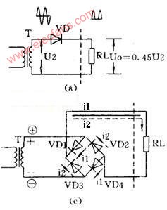
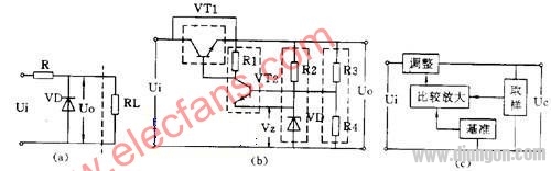
The half-wave rectifier circuit requires only one diode, see Figure 2 (a). VD is turned on during the positive half cycle of the alternating current, VD is cut off in the negative half cycle, and the pulsating direct current is obtained on the load R.

(2) full wave rectification
Two-diode is used for full-wave rectification, and the transformer is required to have two secondary coils with the same number of turns with a center tap, see Figure 2 (b). What is obtained on the load RL is a pulsating full-wave rectified current, and the output voltage is higher than that of the half-wave rectifying circuit.
(3) full wave bridge rectifier
A bridge rectifier circuit consisting of 4 diodes can use a transformer with only a single secondary coil, see Figure 2 (c). The current waveform and output voltage value on the load are the same as the full-wave rectifier circuit.
(4) voltage doubler rectification
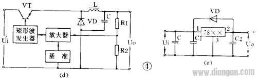
Higher DC voltages can be obtained with multiple diodes and capacitors. Figure 2 (d) is a double voltage rectifier circuit. When U2 is negative half cycle, VD1 is turned on, C1 is charged, and the highest voltage on C1 can be close to 1.4U2. When U2 is halfway, VD2 is turned on, and the voltage on C1 and U2 are superimposed to charge C2, so that the voltage on C2 is close. 2.8U2 is twice the voltage on C1, so it is called double voltage rectifier circuit.
Third, the filter circuit
After rectification, the pulsating direct current is obtained. If a filter circuit is added to filter out the alternating current component in the pulsating direct current, a smooth direct current can be obtained.
(1) Capacitor filtering
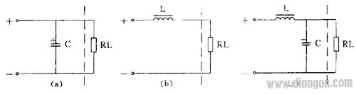
Connect the capacitor in parallel with the load. As shown in Figure 3 (a), the capacitor is charged during the positive half cycle and the capacitor is discharged during the negative half cycle to obtain a smooth DC current on the load.
(2) Inductive filtering
Connecting the inductor to the load in series, as shown in Figure 3 (b), also filters out the AC component of the ripple current.
(3) L, C filtering
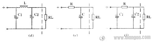
A filter circuit consisting of 1 inductor and 1 capacitor is called an L-shape because it is like an inverted letter "L", see Figure 3 (c). A filter circuit with 1 inductor and 2 capacitors is called π type because of the letter "π", as shown in Fig. 3 (d), which is a circuit with better filtering effect.
(4) RC filtering
Inductors are costly and bulky, so resistors are often used in electronic circuits where current is not too large to form an RC filter circuit. Similarly, it also has an L-shape, see Figure 3 (e); π-type, see Figure 3 (f).
Fourth, the voltage regulator circuit
Fluctuations in the AC grid voltage and changes in the load current cause the output voltage and current of the rectified power supply to fluctuate accordingly. Therefore, a higher power electronic circuit must use a regulated power supply.
(1) Zener diode shunt regulator circuit
A circuit with a Zener and load in parallel is the simplest regulator circuit, see Figure 4 (a). In the figure, R is a current limiting resistor. The output current of this circuit is very small, and its output voltage is equal to the stable voltage value VZ of the Zener diode.
(2) series regulator circuit
A series regulator circuit with amplification and negative feedback is the most commonly used regulator circuit. Its circuit and block diagram are shown in Figures 4 (b), (c). It detects the change of the output voltage from the sampling circuit (R3, R4), compares it with the reference voltage (VZ) and amplifies it by the amplifier (VT2) and applies it to the adjusting tube (VT1) so that the voltage across the adjusting tube Variety. If the output voltage drops, the voltage drop of the adjustment tube is also lowered, and the output voltage is raised. If the output voltage rises, the voltage drop of the adjustment tube is also increased, so that the output voltage is depressed, and the output voltage is substantially unchanged. . On the basis of this circuit, it has developed into many variant circuits or added some auxiliary circuits, such as a composite tube as an adjustment tube, an output voltage adjustable circuit, an operational amplifier for comparative amplification, and an auxiliary power supply and overcurrent protection circuit. Wait.
(3) Switching regulator circuit
The new regulated power supply widely used in recent years is a switching regulator power supply. Its adjustment tube works in the switching state, its own power consumption is very small, so it has the advantages of high efficiency, small size, etc., but the circuit is more complicated.
There are many different types of switching regulators. Its basic block diagram is shown in Figure 4 (d). In the figure, inductor L and capacitor C are energy storage and filter components, and diode VD is a freewheeling diode that provides a current path for the L and C filters when the regulator is in the off state. The switching frequency of the switching power supply is very high, generally several to several tens of kilohertz, so the volume of the inductor is not large, and there are not many high harmonics in the output voltage.
Its basic working principle is: From the sampling circuit (R3, R4), the sampling voltage is detected and amplified to control a rectangular wave generator. The output pulse of the rectangular wave generator controls the conduction and cut-off time of the regulating tube (VT). If the output voltage U 0 decreases due to fluctuations in the grid voltage or load current, the output pulse of the rectangular wave generator is widened, so that the conduction tube conduction time is increased, so that the L and C tank circuits obtain more energy. As a result, the output voltage U 0 is boosted to achieve a stable output voltage.
(4) Integrated voltage regulator circuit
In recent years, a large number of integrated voltage regulator products have been introduced, with many varieties and different structures. At present, there are three-terminal integrated voltage regulators, such as the CW7800 series that output positive voltage and the CW7900 series that output negative voltage. The output current is from 0.1A to 3A, and the output voltage is 5V, 6V, 9V, 12V, 15V, 18V, 24V, etc.
This integrated regulator has only three terminals, and all parts of the regulator circuit, including the high-power adjustment tube and protection circuit, are integrated into the chip. When you use it, just add the heat sink and connect it to the rectifier filter circuit. There are few external components, high voltage regulation accuracy, reliable operation, and generally no debugging is required.
Figure 4 (e) is a three-terminal regulator circuit. In the figure, C is the main filter capacitor, C1 and C2 are the capacitors for eliminating parasitic oscillations, and VD is the protection diode used to prevent the input short circuit from burning out the integrated block.
Five, power circuit reading map points and examples
A power circuit is a relatively simple but widely used circuit in an electronic circuit. When you get a power supply circuit diagram, you should: 1 Decompose the entire power supply circuit in the order of “rectification-filtering-stabilization†and analyze it step by step. 2 In the step-by-step analysis, the main circuit and auxiliary circuit, main components and secondary components should be distinguished, and their functions and parameter requirements should be clarified. For example, in a switched regulated power supply, the inductor and the freewheeling diode are the key components. 3 Because transistors have NPN and PNP types, some integrated circuits require dual power supplies, so a power supply circuit often includes different voltage values ​​and several sets of outputs. The values ​​and polarities of the output voltages of each group must be distinguished when reading the picture. Carefully distinguish the polarity of the transistors and electrolytic capacitors during assembly and repair to prevent errors. 4 Familiar with some customary techniques and simplified drawing. 5 Finally, the entire power supply circuit is fully integrated from front to back. This power circuit diagram is also understood.
Example 1 Electric blanket temperature control circuit
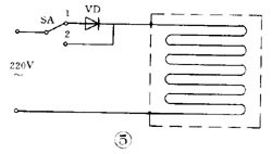
Figure 5 is an electric blanket circuit. The switch is in the low temperature range at the "1" position. After 220 volts, the electric power is connected to the electric blanket through the diode. Because it is half-wave rectification, the pulsating direct current of about 100 volts is applied to both ends of the electric blanket. The heat is not high, so it is insulated or low temperature. When the switch is turned to the "2" position, the 220V mains is directly connected to the electric blanket, so it is a high temperature file.
Example 2 High-voltage electronic mosquito killer
Figure 6 shows a small-current DC high-voltage electric mosquito killer using the voltage doubler rectification principle. The 220 volt AC is rectified by quadruple voltage and the output voltage is up to 1100 volts. This DC high voltage is applied to the parallel wire mesh. The bait is placed under the net, causing a short circuit when the fly stops on the net, and the high voltage on the capacitor kills the fly through the body discharge of the fly. After the fly corpse falls, the capacitor is charged again and the grid is restored to high voltage. This high-voltage grid has a small current and is therefore harmless to humans.
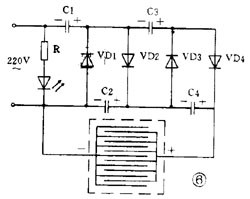
Because insects have phototaxis at night, if you put a 3 watt fluorescent lamp or a small black light behind the grid, you can trap mosquitoes and harmful insects.
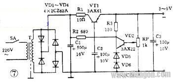
Example 3 Practical regulated power supply
Figure 7 is a practical regulated power supply. The output voltage is adjustable from 3 to 9 volts and the output current is up to 100 mA. This circuit is a series-type regulated power supply circuit. It should be noted that: 1 The drawing of the rectifier bridge is different from that of Figure 2 (c). In fact, it is a bridge rectifier circuit. 2 This circuit uses a PNP-type manifold, so the output is a negative voltage and the anode is grounded. 3 Replace the Zener diode with two common diodes. The forward voltage drop of any diode is essentially constant, so a diode can be used instead of a Zener. The forward voltage drop of the 2AP diode is about 0.3 volts, the 2CP type is about 0.7 volts, and the 2CZ type is about 1 volt. Two 2CZ diodes are used as reference voltages. 4 The sampling resistor is a potentiometer, so the output voltage is adjustable.
Guangdong Ojun Technology Co., Ltd. , https://www.ojunconnector.com