
Convert code to voltage
The ADC sampled analog signal provides a quantized digital code representing the input signal. The digital output code is post-processed and the results can be reported to the operator who used the information to make decisions and take action. Therefore, it is important to correlate the digital codes correctly with the analog signals they represent.
In general, the ADC input voltage is related to the output code by a simple relationship, as shown in Equation 1:
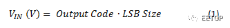
Where VIN (V) is the input voltage to the ADC (referred to as the input, as described below), the output code is the digital output code (count) of the ADC's decimal format, and the LSB size is the least significant bit (LSB) in the ADC code.
Equation 1 is a general formula that can be used with any ADC. It does not matter if the output code of the ADC is in binary or twos complement format, as long as the binary number is correctly converted to its equivalent decimal value.
Determine the LSB size
After the ADC conversion is completed, the input voltage is calculated by multiplying the decimal value of the output code by the LSB size. Knowing the LSB size is the key to switching between code and voltage.
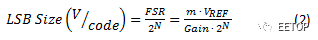
Equation 2 determines the LSB size:
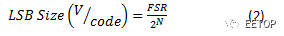
Where FSR is the full-scale input range (in volts) of the ADC proportional to the reference voltage, and N is the number of bits in the ADC output code. 2N is equal to the total number of ADC codes.
The LSB size is equal to the full-scale input range (FSR) divided by the total number of ADC codes. This is equivalent to the step size of each code required to cover the entire input range. Figure 1 shows the step function of a 4-bit ADC (24 = 16 codes) that maps the input voltage to the output code.
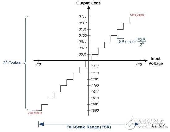
Figure 1 : ADC Input Transfer Function ( N = 4 )
Full scale range and input reference voltage
Pay attention to the FSR of the ADC used, because different ADCs have different FSRs. The FSR is always proportional to the reference voltage and may also depend on any internal gain, as shown in Equation 3:
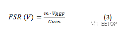
Where VREF is the reference voltage of the ADC (in volts); m is the reference voltage scaling factor (for example, if the differential input range of the ADC allows the input voltage to be from -VREF to VREF, then m = 2, hence FSR = 2VREF), the gain Is the internal gain of the ADC (if any, otherwise 1V / V). I included the gain in this formula to calculate the input reference voltage if the ADC contains a gain stage, as shown in Figure 2.
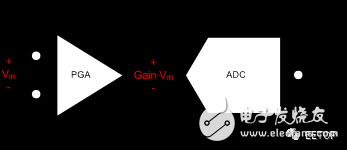
Figure 2 : Input Reference Voltage
The delta-sigma ADC typically integrates a programmable gain amplifier (PGA) gain stage prior to the ADC input; this is why Equation 3 includes the gain term. By including the PGA gain in the FSR calculation, the LSB size calculation also takes this gain into account. This means that when the output code is multiplied by the LSB size, the result is the input reference voltage (VIN) before the PGA input, as shown in Figure 2, rather than the amplified (output reference) voltage. Note that if the system uses additional signal conditioning before the ADC, the effect of this circuit may require additional calculations to determine the system's input reference voltage (before the signal conditioning circuit).
Sample code
In most cases, the ADC code is read by the microcontroller in 8-bit segments and concatenated into a 32-bit data type. If the resolution of the ADC is less than 32 bits and the output code is signed, you need to extend the data symbol to a 32-bit integer data type to preserve the symbol. The code in Figure 3 is an example of this operation.
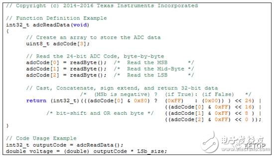
Figure 3 : Code example for reading 24 -bit ADC data
In the previous Buffon, I explained how to calculate the input voltage of an analog-to-digital converter (ADC) by multiplying the output code of the ADC by the least significant bit (LSB) size using Equation 1:

To calculate the LSB size of the ADC, we use Equation 2:
Â
Now that you know how to calculate the input voltage from the output code, let's look at a few common application examples that use a delta-sigma ADC to show how the relevant physical parameters are calculated from the measured voltage. With each example, I provide a link to the TI Designs reference design where you can get additional design assistance.
Current shunt measurement
The ADC measures the voltage; therefore, you must first convert the current to a voltage. The easiest way is to force the current through a resistor with a known value, as shown in Figure 1.
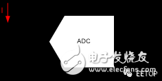
Figure 1 : Current shunt measurement
The relationship between current and voltage is given by Ohm's law (V = I∙R). To get the current amplitude I, multiply the measured voltage on the ADC by the resistor VR and divide it by the resistor R, as shown in Equation 3:
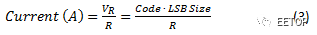
Ensuring accurate current measurement requires an accurate and stable shunt resistor. Other design considerations can be found in the TI Designs Voltage and Current Measurement Reference Design for Automotive Vehicle Charger Systems ( TIDA-00456 ).
RTD temperature measurement
A resistance temperature detector (RTD) is a temperature sensor with temperature dependent resistance. The ADC indirectly measures the RTD resistance and infers the RTD temperature. The measurement configuration is similar to that of Figure 1, except that the known field current IExcite is forced through the resistor to generate a voltage. This current can also produce a reference voltage for the ADC, making it proportional to the measurement, as shown in Figure 2.
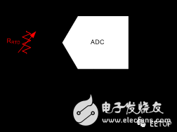
Figure 2 : Proportional RTD measurement
To calculate the RTD resistance, RRTD, divide the measured voltage VRTD by the excitation current IExcite, as shown in Equation 4:

The accuracy of the current source usually affects the accuracy of the resistance measurement; however, by using the proportional configuration shown in Figure 2, you can eliminate this dependency. Note how the LSB size is proportional to the excitation current, as shown in Equation 5:
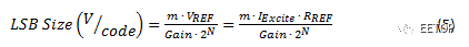
Substituting Equation 5 into Equation 4 results in a proportional relationship that does not depend on the magnitude of the excitation current, as shown in Equation 6:

The accuracy of the measurement now depends mainly on the stability of the reference resistor, which is usually better than the stability of the field current. This configuration is called a proportional calculation because the output code of the ADC is proportional to the ratio of the RTD to the reference resistance.
The RTD resistance is known, but you still have to determine the temperature of the RTD. Equation 7 uses the Callendar-Van Dusen equation to specify the relationship between temperature and RTD resistance:

Where T is the RTD temperature; A, B, and C are the standard polynomial coefficients given by the RTD type; R0 is the nominal resistance of the RTD at 0 °C. Note that for temperatures above 0°C, you can simplify Equation 7 to solve the temperature directly, as shown in Equation 8:

In the case where only a small temperature range is used, a linear approximation is performed to simplify the temperature calculation. Alternatively, you can use a software reference lookup table to convert RTD resistance to temperature without solving polynomial equations.
An example of a RTD measurement using a lookup table can be found in the TI Designs RTD Temperature Transmitter for a 2-wire, 4 to 20 mA current loop reference design ( TIDA-00095 ).
Thermocouple temperature measurement
A thermocouple is a temperature sensor that produces a temperature-dependent voltage output proportional to the temperature difference between the two connectors: sensing/hot junction and reference/cold junction. The ADC measures this voltage and converts it to a relative temperature (temperature difference), as shown in Figure 3.
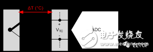
Figure 3 : Thermocouple measurement
To determine the absolute temperature at the inductive junction, TSense adds the relative temperature to the reference junction temperature, TRef, which must be known by controlling its temperature or by other methods of measuring the temperature. Once the ADC measures the input voltage, the absolute temperature of the thermocouple is calculated using a polynomial equation, as shown in Equation 9:

The coefficients c0, c1, c2, ..., cN are standard polynomial coefficients specific to the type of thermocouple and the associated temperature range. In many cases, using a lookup table is more convenient than solving Equation 9, which may have extremely high order.
An example of using a thermocouple measurement lookup table can be found in the TI Designs Thermocouple AFE Reference Design ( TIDA-00168 ) using RTD or integrated temperature sensor for cold junction compensation (CJC) .
Load cell measurement
The load cell consists of a combination of resistors of a bridge structure, some of which (strain gauges) vary in resistance based on the applied load (or weight), as shown in Figure 4.
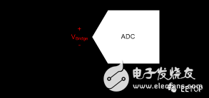
Figure 4 : Load cell measurement
The resistor bridge provides an output voltage that is proportional to the excitation voltage and the applied load. Even if the applied load changes the resistance of the strain gage, there is no need to measure the resistance due to the very linear relationship between the applied load and the output voltage, as shown in Equation 10:

Where, the applied load (kg) is the weight on the load cell; the load capacity (kg) is the rated weight capacity of the load cell; VExcite (V) is the excitation voltage applied to the load cell; and the sensitivity (mV/ V) (rated output) is a specified parameter given by the load cell manufacturer that indicates the output voltage of the load cell at full capacity with a 1V excitation voltage.
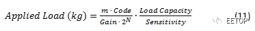
Note that the change in excitation voltage has a direct effect on the measurement result; therefore, the excitation voltage is typically used as the reference voltage to make the measurement proportional, independent of the excitation voltage. When the reference voltage is equal to the excitation voltage, calculate the weight using Equation 11:
Other design considerations and techniques for improving weighing accuracy can be found in TI Designs' high-resolution, low-drift, precision weighing reference designs with AC bridge excitation ( TIPD188 ).
KNM2 Series Moulded Case Circuit Breaker
KNM2 series Moulded Case Circuit Breaker is MCCB , How to select good Molded Case Circuit Breaker suppliers? Korlen electric is your first choice. All moulded Case Circuit Breakers pass the CE.CB.SEMKO.SIRIM etc. Certificates.
Moulded Case Circuit Breaker /MCCB can be used to distribute electric power and protect power equipment against overload and short-current, and can change the circuit and start motor infrequently. The application of Moulded Case Circuit Breaker /MCCB is industrial.
Korlen electric also provide Miniature Circuit Breaker /MCB. Residual Current Circuit Breaker /RCCB. RCBO. Led light and so on .
KNM2 series Molded Case Circuit Breaker,KNM2 series Small Size Molded Case Circuit Breaker,KNM2 series Electrical Molded Case Circuit Breaker,KNM2 series Automatic Molded Case Circuit Breaker
Wenzhou Korlen Electric Appliances Co., Ltd. , https://www.korlenelectric.com