
The preparation of the grounding system in the dcs application, the most unclear, but must understand is probably the grounding problem. Not only are many users unclear, but some system integrators and DCS vendors are not necessarily clear, because most people who learn automatic control and computers do not learn automatic control principles or computer principles at school. Learn the grounding content. The industrial control computer involves many types of signal lines in addition to the computer itself, which are directly connected to the computer I/O interface. These signals are of a switching type (including opening, opening, and load capacity). The difference is analog (large signal: 4-20mV, 1-5V, small signal 0-50mV. O-10mV, there are four-wire system in large signal, there are also two-wire system). Some systems also have communication. The signal is directly connected to the computer's AC signal through the transformer, which causes various industrial computer manufacturers (especially DCS manufacturers) to propose various kinds of operations in order to ensure that their systems can operate normally in various application sites. Grounding requirements. These grounding requirements vary widely, some are very demanding, and some are relatively loose. This makes the field personnel more confused. Not only the grounding requirements of the manufacturers are inconsistent, but also the grounding of various textbooks and design manuals. The explanation is not uniform. In order to let the on-site construction personnel and engineering service personnel have a more comprehensive understanding of the grounding problem, we will introduce a system in more detail here. Some grounding concepts and methods encountered in use.
1. Causes of interference In order to understand the purpose of grounding, we first introduce several types of interferences encountered in system applications. Interference, also known as noise, is a signal-independent electrical signal that is inserted into or superimposed on the system power and signal lines. Interference can cause measurement errors and serious interference (such as lightning strikes. Large series mode interference can cause equipment damage. Common interferences are as follows:
(1) Interference introduced by resistance coupling (conduction introduction)
1 When several kinds of signal lines are transmitted together, due to the aging of the insulating material, the leakage affects other signals, that is, the interference is introduced in other signals.
2 In some control systems that use electrical energy as a means of execution (such as electric furnaces, electrolyzers, etc.), the signal sensor leaks and contacts the charged body, which also introduces a large amount of interference.
3 In some old-fashioned instruments and actuators, the field end uses 220V power supply, sometimes the equipment burns out, causing a short circuit between the power supply and the signal line, which will also cause large interference.
4 Because the grounding is unreasonable, for example, grounding at both ends of the signal line, a large interference will be added due to the ground potential difference, as shown in Figure 3.4.9. Both ends of the signal line are grounded at the same time. Thus, if the distance between the two points A and B is far, there may be a large potential difference eN. This potential difference may be generated on the signal line between the ends of A·B. A big circulation.
(2) Interference introduced by capacitive inductive coupling 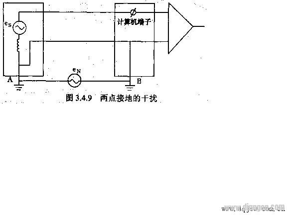
Because there are often many signals connected to the computer at the controlled site, and these signal lines either go through the cable trough or take the cable tube, but certainly many signals are wired together. There are distributed capacitances between these signals, and the distributed capacitance is used to add interference to other signal lines. At the same time, an alternating magnetic flux is generated around the alternating signal lines, and these alternating magnetic fluxes will An electromotive force is generated between the parallel conductors, which also causes interference on the line.
(3) Interference introduced on computer power supply lines In some industrial sites (especially power plant metallurgical enterprises, large mechanical processing plants), large-scale electrical equipment starts frequently, and large switching devices operate more frequently. The starting and closing of these motors are closed. The resulting spark creates a large alternating magnetic field around it. These alternating magnetic fields can either generate interference by coupling on the signal line or generate high-frequency interference through the power line. If the interference exceeds the allowable range, it will affect the operation of the computer system.
(4) Interference lightning strikes introduced by lightning strikes may cause large electromagnetic interference around the system, and may also introduce interference through various grounding lines.
2. Interference suppression The above lists several causes of interference. If these interferences are not well suppressed and prevented, it will affect the accuracy of the measurement technology of the system, thus making normal control impossible, and causing equipment damage. People have summarized many methods of interference suppression in long-term engineering practice.
(l) Isolation 1 so that all signal lines are well insulated, making it impossible to leak electricity, thus preventing interference introduced by contact;
2 Isolation and laying of different kinds of signal lines (in different cable troughs or separated by partitions), we can divide them according to the different types of signals according to the ability of anti-noise interference.
Analog signals (mode, touch, especially low-level analog signals such as thermocouple signals, thermal resistance signals, etc.) have poor anti-interference ability to high-frequency pulse signals. It is recommended to use shielded twisted pair connections, and these signal lines must occupy the conduit or cable trough separately. Do not route other signals in the same cable duct (or slot).
Low-level switching signals (some state dry junction signals), data communication lines (RS232, EIA485, etc.), the anti-interference ability of low-frequency pulse signals is stronger than the above signals, but it is recommended to use shielded twisted pairs (at least Connect with twisted pair). Such signals should also be routed separately, and should not be paralleled with the power line and the large load signal line.
High-level (or high-current) switching input and output, CATV, telephone line, and other relay input and output signals, these signals have stronger anti-interference ability than the above two, but these signals will interfere with other signals. It is therefore recommended to use twisted pair connections and separate cable tubes or cable trays.
Power line AC 220V, 380V, and circuit breakers and switch signal lines with large on-off capability. The cable selection of these lines is mainly determined by the anti-interference ability, but by the current load and withstand voltage level.
As explained above, the same type of signal may be placed in a cable duct or slot. If similar types of signals must be routed in the same cable trough, they must be separated by a metal partition.
3 Another type of isolation is to electrically isolate the signal source from the computer, thus greatly reducing the harm caused by common mode interference to the computer. As shown in Figure 3.4.10. Figure 3.4.10 shows that the input terminal of the signal is completely isolated from the computer part by an isolation amplifier (some systems use isolation transformers or relays to isolate them, and the switching quantity can be isolated by optoelectronic devices or relays). In this way, the interference signal generated by the difference in ground potential between C and D does not form a loop, which suppresses the harm of interference. 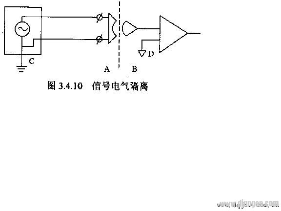
4 The fourth isolation is the isolation of the power supply system In order to prevent the introduction of common mode high frequency interference signals on the power supply line, an isolation transformer can be provided on the power supply line for interference isolation, as shown in Figure 3.4.11.
In order to achieve good interference suppression, there are two points that must be noted:
· The shield of the transformer should be well grounded;
• The secondary winding of the transformer must be twisted pair.
(2) Shielding is to use a metal conductor to surround the shielded components, assemblies, telephone lines, and signal lines. This method works well for capacitive coupling noise suppression. The most common is to connect the analog signal with a shielded twisted pair.
The above mentioned electrical shielding, but in many cases, in addition to the interference of electrical noise, the signal is mainly affected by strong alternating magnetic fields, such as power stations, smelters, heavy machinery factories, etc., then, in addition to electrical shielding, Also consider magnetic shielding, that is, consider shielding with a conductor with good magnetic permeability such as iron or nickel.
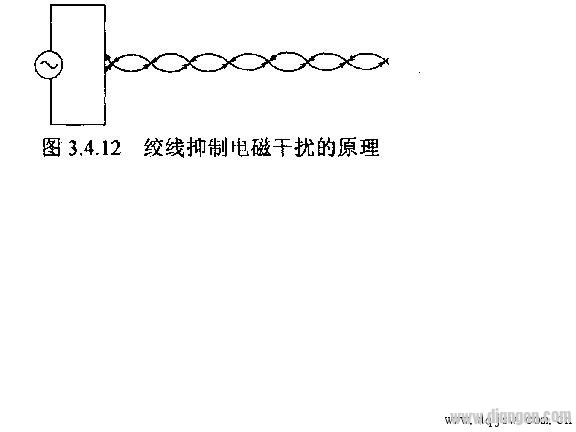
(3) Replacing two parallel wires with twisted pairs is an effective way to suppress magnetic field interference. The principle is shown in Figure 3.4.12: 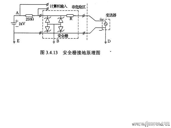
In Figure 3.4.12, each small twisted pair ring will pass alternating magnetic flux, and these varying magnetic flux will generate an electromotive force in the surrounding conductor, which is determined by the law of electromagnetic induction (as shown in the wire in the figure). The arrow shows). It can be seen from the figure that the electromotive forces generated on the same conductor in the adjacent twisted-ring rings are opposite in direction and cancel each other, which has a good inhibitory effect on electromagnetic interference.
(4) Lightning strike protection system is affected by lightning strikes in two ways: overhead power line, signal line may be struck by lightning, and the other is lightning strike near the signal cable, coupled to the signal line through distributed capacitance and inductance, generated on the signal line A large pulse of interference, sometimes even burning equipment, affecting personnel safety. For different interference reasons, the following two measures can be used to prevent lightning strikes:
1 For coupling interference, we can lay the signal line with metal cable tube or slot, and the cable tube or metal slot has good grounding.
2 For overhead signal lines, lightning protection measures must be taken at the computer input terminals, such as lightning arresters, pressure sensitive resistors, and strong filter circuits to suppress interference.
3, grounding preparation (l) the role of grounding The role of the grounding There are only two types of steps: protect people and equipment from damage; suppress interference; inhibit interference grounding in some books, also called work ground, and the former is called protection Ground.
1 Protective earthing protection The grounding is to form a good conductive connection between the metal parts of the DCS (the cabinet housing, the console housing, etc.) and the ground to protect the equipment and personal safety. The reason is that the DCS power supply is a strong power supply (220V or 11OV). Under normal circumstances, the chassis is not charged. When a fault occurs (such as a host power failure or other fault), the power supply of the power supply is short-circuited with the conductive metal parts such as the casing. When these metal parts or casings form a charged body, if there is no good grounding, there is a high potential difference between the charged body and the ground. If someone accidentally touches the charged body, then it will pass. The human body forms a pathway that creates danger. Therefore, it is necessary to make a good connection between the metal casing and the ground so that the casing and the ground are equipotential. In addition, the protective grounding also prevents the accumulation of static electricity.
2 Working grounding Working grounding is the grounding provided for the DCS and the instruments connected to it to operate reliably and to ensure measurement and control accuracy. It is divided into machine logic ground, signal loop grounding, shield grounding, and intrinsically safe grounding in petrochemical and other explosion-proof systems.
The machine logic ground, also called the host power supply ground, is the logic level negative internal common ground of the computer, and is also the output ground of the power supply such as +5V.
· Signal circuit grounding, such as the negative terminal of each transmitter is grounded, and the negative terminal of the switching signal is grounded.
• Shield grounding (grounding of the shield of the human signal).
· Intrinsically safe grounding is the grounding of the intrinsically safe instrument or safety barrier. In addition to suppressing interference, this type of grounding has one of the measures to make instruments and systems inherently safe. The intrinsic safety grounding will be different depending on the actual measures of the equipment used. The Zener safety barrier is taken as an example to illustrate the grounding content, as shown in Figure 3.413: This figure is the grounding of a Zener safety barrier. Schematic. 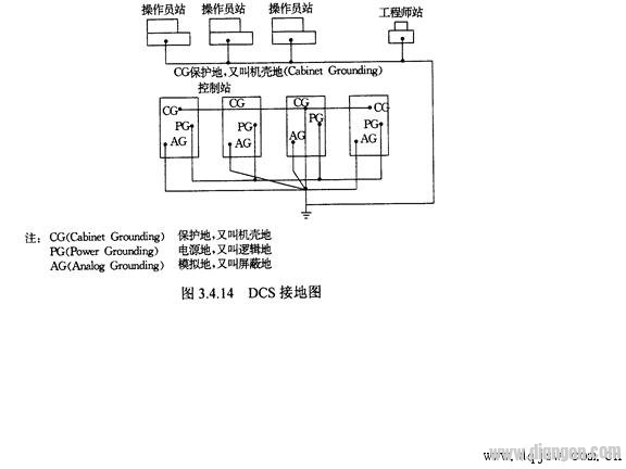
The purpose of the barrier is to protect the hazardous field end from being within safe power and safety voltages. If the field terminal is short-circuited, the current on the wire will be limited to a safe range due to the current limiting of the load resistance and the safety barrier resistance R, so that the field end does not generate a high temperature and cause combustion. In the second case, if a fault occurs at one end of the computer, the high-voltage electrical signal is added to the signal loop, and the voltage is in a safe range due to the clamping action of the Zener secondary.
It is worth reminding that due to the introduction of the Zener barrier, the resistance on the signal loop is greatly increased. Therefore, in designing the load capacity of the output loop, in addition to considering the real load requirements, the safety barrier must be fully considered. The resistance, leaving room for it.
In addition to the above-mentioned grounding, in many cases, there is also a power supply system, also called AC power supply working ground, which is the grounding required for operation in the power system (such as neutral grounding).
(l) Grounding requirements and methods:
The six types of grounding are described above: power supply system ground, protection ground, logic ground, shielded safety ground, and signal loop ground. For these six kinds of grounding, each family has its own requirements. Although most of them emphasize a little grounding, the grounding resistance must be less than 1 ohm, etc., but the details vary greatly. Several examples are given below to describe the commonly encountered grounding requirements and method.
1 Power supply system: In many enterprises, especially power plants, smelters, etc., there is a large ground network in the factory area, and usually the ground of the power supply system is connected with the ground network. Some manufacturers emphasize that all grounding of the computer system must be strictly separated from the power supply system and other (such as lightning protection), and at least 15m distance should be maintained. In order to completely prevent the influence of the power supply system, it is recommended that the power supply line be separated by an isolation transformer. This should be noted for those units where the electrical load is heavy and the load is often started and stopped. From the standpoint of suppressing interference, it is advantageous to separate all of the power system from the computer system because the ground of the general power system is not very clean. However, from an engineering point of view, it is very difficult to separate the computer system and ensure that it is separated from the power supply system in some occasions. In this case, it can be considered whether the computer system ground and the power supply ground can be shared. There are several factors to consider: #p#分页头#e#
· Whether the power supply system has large interference on the ground, such as whether the high-current equipment starts and stops frequently, and whether the interference to the ground is large;
· Is the grounding resistance of the power supply system small enough, and whether the potential difference of each part of the ground network is small, that is, whether the resistance between the parts of the ground network is small (<1W)
The DCS's anti-interference ability and the anti-interference ability of the transmitted signal used, such as the presence or absence of small signals (galvanic couples, thermal resistance).
2 The grounding involved in all computer wiring uses a one-point grounding method. At this point, there is also a lot of controversy. Some manufacturers have proposed several places: logical ground, shielded ground (also called analog ground), signal ground, and protective ground, respectively, grounded on the ground to ground the device, and most systems indicate that the grounding is grounded separately in the cabinet. , sink at a point, then use the thicker conductor (copper) to pick up the sinks and connect them to a common grounding body. Here are a few points to note:
The DCS itself is composed of multiple devices. In addition to the control station, it also includes many peripherals, and there is more than one data. This involves multiple devices and multiple grounding problems. In addition, the power supply of the general DCS is that each station (control station, operation station, etc.) is separately powered by a dedicated line, that is, not mutually powered. Figure 3.4.14 is a commonly used multi-station grounding diagram.
Protective earthing: All equipment of DCS has a protective ground. This protection is usually connected internally when the cabinet and other equipment are designed and processed. In some systems, the protective ground has been protected inside the power supply line. The middle head of the three-pin plug is connected together, and some do not allow the protective ground to be connected to the line. The user must carefully read the grounding installation instructions provided by the manufacturer. In either case, the CG must have one device (control station, The operator station, etc.) all the peripherals or system CG are connected together, then the CG of each station is connected by a thick insulated copper wire, and finally connected to the earth grounding system from one point. It is also worth noting that all peripherals of the DCS must be powered from one supply line, and one device (such as all peripherals and host systems connected to the operator station (CRT, printer, copy machine) The power supply must be powered from the power distributor of the device, and not allowed to take power from other places, otherwise the interface or even the device may be burned out. For those who have to connect with long wires, or use thicker wires to provide power, or take communication. Isolation measures.
The CG of each station can be connected by a radiation connection method or a serial connection method. The power logic ground (P) is shown in Figure 3.4.14. First, the logic ground in each station must be located at a point PG, and then the thick insulated wire is radiated to a point and then to the earth ground line. In some systems, all inputs and outputs are isolated, so that the internal logic is a separate unit, and there is no electrical connection with other parts. In this system, PG grounding is not required, but the internal floating is kept. Therefore, users must carefully read the technical requirements and grounding requirements of the product when designing and constructing the grounding system.
Analog ground (AG), analog ground (also called shield ground) is the most demanding of all grounding. Almost all systems have proposed that the AG is grounded at one point and that the grounding resistance is less than IQ. In DCS design and manufacturing, AG bus bars or other facilities are placed inside the cabinet. When the user connects, connect the shielded wires to the AG busbars. Connect them to the bottom of the cabinet with insulated copper plaques, and then connect the junction points of the cabinets with insulating copper or copper bars. location. Most DCS require that not only the AG ground resistance of each cabinet is <I ohms, but also the resistance between the cabinets is <1 ohm.
• Signal ground processing: In principle, each transmitter and other sensors are not allowed to be grounded at the field end, and their negative ends should be grounded at the computer terminals. However, in some cases, the field end must be grounded. At this time, it must be noted that the input terminal (upper double end) of the original signal must not be electrically connected to the ground wire of the computer. The computer must use the front end when processing such signals. Effective isolation measures.
· Grounding of the safety barrier: Let us look back at the safety barrier circuit diagram shown in Figure 3.4.13. It can be seen from the figure that there are three grounding points: B, E, D, usually both B and E are on the computer side. Can be connected together to form a little ground. The point D is the grounding of the transmitter casing in the field. If there is a potential difference between the two grounding points of the field and the control room, then the potentials of points D and E are different. Suppose we use E as the reference point, assuming that the potential of 10V appears at point D. At this time, the potential of point A and point E is still 24V, then there may be a potential difference of 34V between A and D, which has exceeded the safe limit potential. Poor, but the Zener tube will not be broken down, because the potential difference between A and E has not changed, so it does not protect. At this time, if the signal line on the site is accidentally hit by the casing, it may cause sparks, which may ignite the surrounding flammable gas. Such a system does not have intrinsic safety performance. Therefore, when designing and implementing a grounding system involving a safety barrier, it is necessary to ensure that the potentials at point D and point B(E) are approximately equal. In the specific practice, the following method can be used to solve this problem: connect the D point and the B point with a thick wire to ensure that the potentials of the D point and the B point are relatively close. The other is to use a unified grounding grid to connect them to the grounding grid. In this way, if the grounding grid has very little resistance, and the better connection is used, the potentials of points D and B can be approximately equal. But be careful, this grounding must not conflict with the above grounding.
Several methods and considerations for grounding are discussed above. In different systems, the configuration requirements for these types of grounding are different, but most systems require less than 1 ohm for the grounding resistance of the AG, and the grounding resistance of the safety barrier should be <4 ohms, preferably <1 ohm, PG. The grounding resistance of the CG and CG should be less than 4 ohms.
(3) Grounding method The grounding system of the general industrial control system (including the automatic instrument) consists of grounding wire grounding busbar, common connecting plate and grounding body. 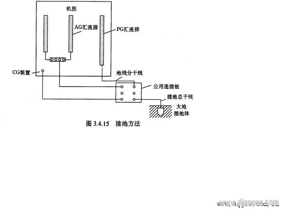
Ring And Fork Type Insulated Terminals
Ring And Fork Type Insulated Terminals,High quality insulated terminal,copper tube terminal
Taixing Longyi Terminals Co.,Ltd. , https://www.longyiterminals.com