
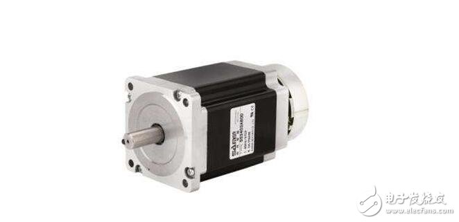
Stepper motor is an open-loop control motor that converts electrical pulse signals into angular displacement or linear displacement. It is the main actuator in modern digital program control systems and is widely used. In the case of non-overload, the speed and stop position of the motor depend only on the frequency of the pulse signal and the number of pulses, and are not affected by the load change. When the stepper driver receives a pulse signal, it drives the stepper motor. The set direction is rotated by a fixed angle called the "step angle" whose rotation is performed step by step at a fixed angle. The angular displacement can be controlled by controlling the number of pulses to achieve the purpose of accurate positioning. At the same time, the speed and acceleration of the motor rotation can be controlled by controlling the pulse frequency, thereby achieving the purpose of speed regulation.
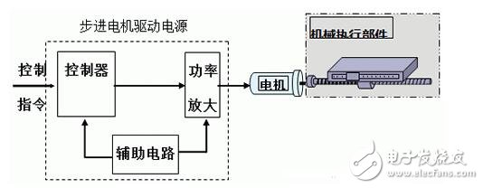
This module can be divided into the following three parts:
· Single-chip system: control stepper motor;
· Peripheral circuit: interface circuit of PIC microcontroller and stepper motor;
· PIC program: Write the interface program of the single-chip microcomputer to control the stepping electric machine to realize the output function of the triangle wave signal.
(1) Interface between stepper motor and single chip microcomputer
The MCU is an excellent control processor. When controlling the stepper motor, the interface components must have the following functions.
1 voltage isolation function.
The MCU works at 5V, while the stepper motor works at tens of V or even higher. Once the voltage of the stepping motor is serialized into the MCU, the MCU will be damaged; the signal of the stepping motor will interfere with the MCU, which may also cause the system to work incorrectly. Therefore, the interface device must have an isolation function.
2 information transfer function.
The interface component shall be able to transmit the control information of the single-chip microcomputer to the stepping motor circuit to generate the control information required for the work. Corresponding to different working modes, the interface component shall be able to generate a corresponding working control waveform.
3 produce the different frequencies required.
In order for the stepper motors to operate at different speeds to suit different purposes, the interface components should be able to produce different operating frequencies.
(2) Voltage isolation interface
The voltage isolation interface is designed to isolate the low-voltage part of the microcontroller and the high-voltage part of the stepper motor drive circuit to ensure their normal operation.
The voltage isolation interface can be a pulse transformer or an opto-isolator, basically using an opto-isolator. The output signal of the single chip microcomputer can be directly sent to the base of the transistor through a TTL gate circuit, and then the light emitting diode of the photoelectric coupling device is driven by the transistor.
The light of the light-emitting diode is turned on the photosensitive tube inside the photoelectric coupling device, converted into an electric signal, and then the power amplifying circuit of the stepping motor is driven, and the current amplifying interface is a pre-amplifying circuit of the stepping motor power amplifier circuit. Its function is to amplify the output signal of the opto-isolator to provide a sufficient driving current to the power amplifier circuit.
(3) working mode interface and frequency generator
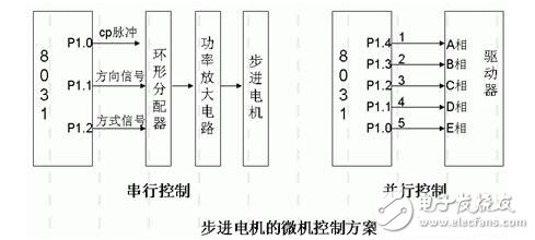
To control the stepping motor with a single-chip microcomputer, it is necessary to control the stepping motor with three I/O lines on the input/output interface. At this time, the single-chip uses the RA0, RAI, and RA2 of the I/O port to control the three-phase of the stepping motor.
Open loop control of stepper motor
1. Hardware control of stepper motor
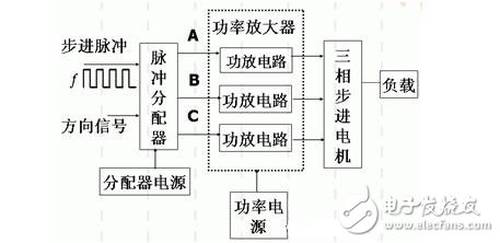
(1) Pulse distributor
When the direction level is low, the output of the pulse divider cyclically generates pulses in the order of ABC.
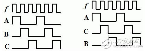
When the direction level is high, the output of the pulse divider cyclically generates pulses in the order of ACB.
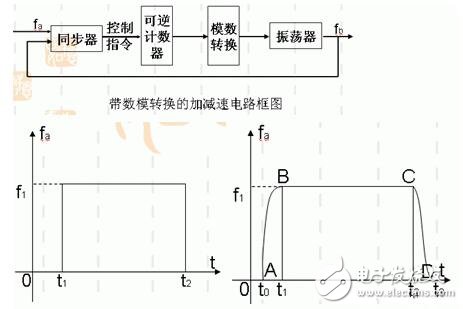
(2) Adding and decelerating control:
(3) Power amplifier
The output signal of the pulse distributor is current amplified to supply power to the stator winding of the motor, so that the rotor of the motor generates output torque.
2. Microcomputer control of stepper motor:
At present, the digital control of the servo system is mostly a combination of hardware and software. The software control method is generally realized by a microcomputer. This is because the digital servo controller based on microcomputer has the following advantages compared with the analog servo controller:
(1) can significantly reduce the hardware cost of the controller. A new generation of microprocessors with faster speeds and newer features are emerging, and hardware costs can be cheap. Small size, light weight and low energy consumption are their common advantages.
(2) The reliability of control can be significantly improved. The mean time between failures (MTBF) of integrated circuits and large scale integrated circuits is much longer than that of discrete component electronic circuits.
(3) The temperature drift of the digital circuit is small, and there is no influence of parameters, and the stability is good.
(4) The hardware circuit is easy to standardize. In the circuit integration process, some shielding measures are adopted to avoid excessive transient current and voltage electromagnetic interference caused by voltage and electronic circuits, so the reliability is relatively high.
(5) Using the digital control of the microprocessor, the two-way transmission capability of the information is greatly enhanced, and it is easy to communicate with the upper system machine, and the control parameters can be changed at any time.
(6) It is possible to design a unified hardware circuit suitable for many power electronic systems, wherein the software can be modularly designed and assembled to form control algorithms suitable for various application objects; to meet different purposes. Software modules can be easily added, changed, deleted, or completely updated as the actual system changes.
(7) Improve the ability of information storage, monitoring, diagnosis and hierarchical control, making the servo system more intelligent.
(8) With the continuous improvement of the computing speed and memory capacity of the microcomputer chip, the control strategy with excellent performance but complex algorithm has the basis of realization.
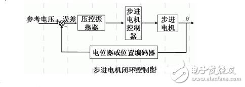
Closed loop control of stepper motor
Stepper motor control strategy
1 PID control
As a simple and practical control method, PID control has been widely used in stepper motor drives. It forms a control deviation e(t) according to the given value r(t) and the actual output value c(t), and linearly combines the proportional, integral and differential of the deviation to form a control quantity, and controls the controlled object. In the literature, the integrated position sensor is used in two-phase hybrid stepping motor. Based on position detector and vector control, an automatically adjustable PI speed controller is designed. Under the condition of variable working condition, the controller can Provides satisfactory transient characteristics. According to the mathematical model of stepper motor, the PID control system of stepper motor is designed. The PID control algorithm is used to obtain the control quantity, thus controlling the motor to move to the specified position. Finally, the simulation proves that the control has better dynamic response characteristics. The use of PID controller has the advantages of simple structure, strong robustness and high reliability, but it can not effectively deal with uncertain information in the system. [2]
At present, PID control is more combined with other control strategies to form a new composite control with intelligence. This intelligent composite control has the ability of self-learning, self-adaptation and self-organization. It can automatically identify the controlled process parameters, automatically adjust the control parameters, adapt to the changes of the controlled process parameters, and at the same time have the characteristics of the conventional PID controller. [2]
2 adaptive control
Adaptive control is a branch of the field of automation that was developed in the 1950s. It is caused by the complexity of the control object, when the dynamic characteristics are unknown or unpredictable changes occur, in order to obtain a high-performance controller. Its main advantages are easy to implement and fast adaptive speed, which can effectively overcome the influence caused by the slow change of the motor model parameters, and is the output signal tracking reference signal. Researchers have derived globally stable adaptive control algorithms based on linear or near-linear models of stepper motors. These control algorithms rely heavily on motor model parameters. The literature combines closed-loop feedback control with adaptive control to detect the position and speed of the rotor. Through feedback and adaptive processing, the driven pulse train is automatically issued according to the optimized lifting and running curve, which improves the drag torque characteristics of the motor. The motor achieves more precise position control and a higher, smoother speed.
At present, many scholars combine adaptive control with other control methods to solve the problem of simple adaptive control. The robust adaptive low-speed servo controller designed in the literature ensures maximum compensation of the arterial moment and low-speed and high-precision tracking control performance of the servo system. The adaptive fuzzy PID controller realized by the literature can adjust the PID parameters online by fuzzy reasoning according to the change of input error and error rate, and realize the adaptive control of the stepping motor, thus effectively improving the response time and calculation accuracy of the system. Anti-interference.
3 vector control
Vector control is the theoretical basis for high-performance control of modern motors, which can improve the torque control performance of the motor. It controls the stator current into the excitation component and the torque component separately by the magnetic field orientation, so that good decoupling characteristics are obtained. Therefore, the vector control needs to control the amplitude of the stator current and the phase of the control current. Since the stepping motor not only has the main electromagnetic torque, but also the reluctance torque generated by the double convex structure, and the internal magnetic field structure is complicated, the nonlinearity is much more serious than that of the general motor, so its vector control is also complicated. In [8], the mathematical model of the dq axis of the two-phase hybrid stepping motor is derived. The rotor permanent magnet flux linkage is the directional coordinate system, so that the direct axis current id =0, the motor electromagnetic torque is proportional to iq, and the PC is used. A vector control system is implemented. The sensor is used in the system to detect the winding current and the position of the motor, and the motor winding current is controlled by PWM. The two-phase hybrid stepping motor model based on magnetic network is derived. The structure of the vector control position servo system is given. The neural network model reference adaptive control strategy is used to compensate the uncertain factors in the system in real time. Torque/current vector control enables efficient control of the motor. [2]
4 Intelligent Control Application
Intelligent control does not rely on or does not rely entirely on the mathematical model of the control object. It only controls according to the actual effect. It has the ability to consider the uncertainty and accuracy of the system in the control, breaking through the framework that the traditional control must be based on the mathematical model. At present, the application of intelligent control in stepper motor systems is relatively mature, which is the integration of fuzzy logic control, neural network and intelligent control.
4 .1 fuzzy control
Fuzzy control is based on the fuzzy model of the controlled object, using the approximate reasoning of the fuzzy controller to achieve the system control method. As a control method that directly simulates the results of human thinking, fuzzy control has been widely used in the field of industrial control. Compared with the conventional control, the fuzzy control does not need an accurate mathematical model, and has strong robustness and adaptability, so it is suitable for the control of nonlinear, time-varying and time-delay systems. The application example of fuzzy control in the speed control of two-phase hybrid stepping motor is given in [16]. The system is advanced angle control, the design does not require a mathematical model, and the speed response time is short.
4 .2 neural network control
Neural networks are methods that utilize a large number of neurons to adjust to a certain topology and learning. It can fully approximate arbitrarily complex nonlinear systems, can learn and adapt to unknown or uncertain systems, has strong robustness and fault tolerance, and thus has been widely used in stepper motor systems. In the literature, the neural network is used to realize the optimal subdivision current of the stepping motor. In the learning, the Bayes regularization algorithm is used, and the weight adjustment technique is used to avoid the multi-layer forward neural network from sinking into the local minimum point, effectively solving the equal step. Corner breakdown problem.
Speed ​​measuring method of stepping motorA stepper motor converts a pulse signal into an angular displacement or a linear displacement.
First, the overload is good. The speed is not affected by the size of the load. Unlike ordinary motors, when the load is increased, the speed will drop. The stepper motor has strict requirements on speed and position.
The second is convenient control. The stepper motor rotates in units of “steps†and the digital features are more obvious.
Third, the structure of the whole machine is simple. The traditional mechanical speed and position control structure is complicated and difficult to adjust. After using the stepping motor, the structure of the whole machine is simple and compact. The tachometer motor converts the speed into a voltage and transmits it to the input as a feedback signal. The speed measuring motor is an auxiliary type motor. A speed measuring motor is installed at the tail end of the ordinary DC motor, and the voltage generated by the speed measuring motor is fed back to the DC power source to achieve the purpose of controlling the speed of the DC motor.
Green Light Hydrogel Screen Protector
Eye protection:The principle of chlorophyll defocusing is adopted to prevent the eyeball from focusing for a long time, effectively alleviate eye fatigue, and achieve better eyesight protection.
Anti-blue light, ultraviolet light:The Green Light Film can actively filter the target wavelength while providing a band in the range of 380-400nm. It can effectively block 100% harmful light.
Edge coverage:The soft material fully covers the edges of any device, so it can be affixed to curved screen and round edges, 100% provides excellent edge coverage, and there is no gap between the edges of the device.
Oleophobic and waterproof:The oleophobic coating surface of the Green Light Screen Protector can provide your phone with oleophobic and waterproof properties, which can prevent sweat, grease residue, and fingerprints.
Sensitive touch:The 0.14mm ultra-thin film does not interfere with the touch response, almost as if it does not exist. When using a mobile phone, the fingertips can be easily swiped, bringing you a comfortable gaming experience.
Green Light Film,Green Light Screen Protector
Shenzhen Jianjiantong Technology Co., Ltd. , https://www.tpuprotector.com