
The 555 timer can conveniently form a monostable flip-flop, a multivibrator, a Schmitt trigger circuit, etc., and the flash circuit is generally controlled by a pulse signal generated by a multivibrator.
First, the circuit diagram is as follows:
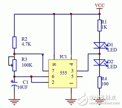
Flash circuit schematic 1
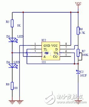
Pin Schematic 2
When analyzing the working principle, it can be compared with Figure 1. This is a typical multi-vibrator designed with 555. Adjusting the variable resistor can change the frequency of the output oscillating signal. The signal outputs a high and low level from pin 3. Control D1 and D2.
When the output is high, D2 is on and D1 is off. When the output is low, D2 does not light and D1 lights up. The overall effect seems to be flashing.
A friend who needs to make a real object can make it according to Figure 2. For such a simple circuit, a small number of components can be purchased and welded with a universal board (hole plate). Of course, when welding, a certain welding technique is required, if welding Friends who are not technically must practice welding technology. We prefer to use drag welding technology in the electronic production process. For specific physical products, refer to Figure 3 and Figure 4.
Second, the list of components is as follows:
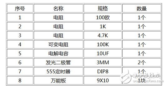
Friends who need to make, can go to the electronic market to buy the above components, are very common components, easy to buy. I recommend to go online to buy, initially estimated that all the materials together, the price is less than 5 yuan.
Third, the flasher physical map
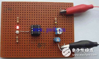
Figure 3 flasher physical map
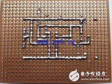
Figure 4 flasher rear line drawing
At the time of production, be sure to pay attention to the pin function of the 555 timer, such as 1 pin grounding, 8 pin power supply, and some ordinary DIP integrated circuits are different. When the production is completed, if the LED light does not flash, it is necessary Detected, first check whether the voltage of pin 1 and pin 8 is normal, then check if the voltage of pin 4 is normal, and whether pin 2 and pin 6 are connected together. If these are normal, the fault will be basically eliminated.
Product Name: Car Charger
Place of Origin: Guangdong, China (Mainland)
Brand Name: OEM
Output Type: DC
Connection: Other
Rated Voltage: 12V-24V
Working Temp: 0-55℃
Weight: 36g
Materials: PC+ABS
Color: White Black
Warranty: 1 year
Suitable for:Most digital devices
SMART PROTECTION & ATTRACTIVE DESIGN ------ Intelligent circuit design protects against short circuiting,over-heating,over-current,and over-charging. Charging stops when battery is full. Car charger with blue LED indicator,which makes it convenient to find exactly where the connection should go; And the light is soft enough not to distract at night.
Dual USB Car Charger Adapter,USB Smart Port Charger ,Car Charger,USB Car Charger For Phone
Shenzhen Waweis Technology Co., Ltd. , https://www.laptopsasdapter.com