
This paper uses the virtual instrument LabVIEW software to develop a software-based traffic light experiment control system to simulate the control of traffic lights, which can realize the traffic light control experiment system without logic control hardware, and can carry out experimental simulation to enable students to master the traffic lights. Software control method. Compared with programmable PLC, single-chip microcomputer and other programs, it enhances the understanding of the software development process and saves the development cost of the test system.
1. Introduction to LabVIEWLabVIEW is a graphical programming language widely accepted by industry, academia, and research laboratories. It is a standard data acquisition and instrument control software. Virtual instrument is a new technology emerging in the 1980s. It is an important direction for the development of modern instrumentation. It has applications in modeling and simulation, design planning and education and training. LabVIEW has the universal functions of various programming platforms. For example, data types, event processing, and loop structures make it a powerful graphical programming tool. LabVIEW is more than just a programming language. Virtual Instruments (VI), each VI, contains a user interface, this interface is called the front panel, generally speaking, the soft panel corresponding to the instrument panel. There is also a back panel, also called a block diagram. The design of the VI includes the design of the front panel and block diagram. The VI is designed to implement the program functions of the software through the design of the front panel and block diagram, using a graphical programming language.
2. Traffic light control system design scheme 2.1, control schemeCrossroad traffic signal traffic lights are usually in three forms of control. The first type is a traditional traffic light, that is, before the green light is switched to the red light, the vehicle is moved to static, and the yellow light is buffered excessively; when the red light is switched to the green light, the vehicle is not over-buffered from static to dynamic; the second is in the traditional traffic light. The green light flashing (referred to as green flashing) function is added on the basis of the control form, that is, the last 3 seconds of the end of the green light period will flash three times, the purpose is to prompt the green light period to end, and to keep the yellow light buffer excessive; the third is digital display The traffic light, that is, the countdown number shows the time of the red, green, and yellow lights. Since the whole process has time display, do not flash the green light, but you can keep the yellow light. The combination of the first and third methods is used in the text.
2.2, front panel designThe intersection control model designed in this paper is set up at the intersection of two east-west lanes and north-south lanes. A traffic signal is set in each of the four directions of the east, west, north and south of the interchange. Each traffic signal consists of three red, yellow and green lights. Open LabVIEW2012 software, create a new VI, and name it traffic light simulation. Right click on the front panel → light → round light, a total of 12 lights, three lights in the north, south and north directions, right click light Open the property and set the color of the light and the light to be off in the appearance. When the light is on, it is red, green and yellow. Not displayed when the light is off. Traffic lights play a vital role in traffic. How to properly set traffic lights is the key to solving traffic problems at intersections. Set the time of the traffic light, set the red light in the north-south direction and the red light time and countdown display in the east-west direction. The former uses numerical input controls, while the latter uses numerical display controls. After setting the display time, right-click the data, click the data operation, click the current value to set the default value, and save the set value. The purpose of this is to save the last set time value after the next experiment system is turned on, otherwise the set value will disappear after the program is closed.
The dramatic increase in the number of cars has put tremendous pressure on urban traffic. Especially during the peak hours of commuting, huge traffic flow makes the road crowded, resulting in unnecessary time wastage and economic loss. Therefore, the intelligent traffic light control system with reliable, safe and convenient design has great practical necessity. The defects of traditional traffic lights are also increasingly appearing. The design is too rigid, and the alternating time of traffic lights is too stylized. It is the most obvious problem that the maximum traffic efficiency of the road is not achieved. In the traditional crossroad traffic control system, only the red, green and yellow lights are used in the direction of the turn control. The real-time situation of the road traffic in all directions and the emergency handling of emergency emergencies are not considered. Unable to achieve optimal traffic command objectives. In order to simulate the actual traffic light control, you can also set the traffic control function in the experimental system to change the lighting time of the traffic lights, such as setting the north-south direction forbidden, letting the traffic flow in the east-west direction or setting the east-west direction to prohibit the north-south direction. The function of the car flow release can be used to implement the design function through the drop-down list control.
2.3, block diagram design2.3.1, traffic lights are running normally
The conditional structure is used on the block diagram interface to determine whether the program enters traffic control, the traffic light works under normal conditions, and if traffic control is not implemented, the program enters the fake branch. There are two sequential structures in the structure palette, which are a tiled sequential structure and a stacked sequential structure. In order to save the program back panel space, a stacked sequential structure is used here. First, 12 Boolean lights (traffic lights) are assigned the value F in the first frame of the cascaded sequential structure, ie the traffic lights are not illuminated. The red light countdown in the north-south and east-west directions is assigned a value of zero. In the second frame, the east-west direction is forbidden, that is, the two green lights in the north-south direction are assigned the value F, and the two red lights in the east-west direction are assigned the value T. The red light countdown in the north-south direction is displayed. The third frame lets the north and south red lights and the east and west green lights go out, giving them a value of F. The fourth frame shows the yellow light in the east-west direction. In the fifth frame, the east-west direction is prohibited, and the north and south directions are passed, that is, the two green lights in the north-south direction are assigned the value T, and the two red lights in the east-west direction are assigned the value F. The countdown to the red light in the east-west direction is displayed. The block diagram of the red light countdown display in the north-south direction is shown in Figure 1.
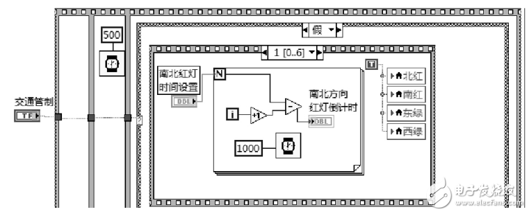
Figure 1 Red light countdown display in the north and south direction
As shown in Figure 1, the red light countdown display time in the north-south direction is the red light setting time in the north-south direction minus the number of cycles. At the same time, the red light is bright in the north and south directions, and the green light in the east and west directions
The sixth frame lets the north-south green light and the red light disappear, and the value is F. The seventh frame shows the procedure for the yellow light in the north-south direction. The yellow light flashing program is shown in Figure 2.
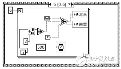
Figure 2 yellow light flashing program branch
2.3.2, traffic control situation
In order to adapt to the actual traffic problems, when implementing traffic control, the traffic light simulation experiment system can still achieve this part of the function. In the block diagram, traffic control is implemented and the program enters the true branch. In the first frame of the cascaded sequential structure, all lights are off, that is, all lamps are assigned the value F. In the second frame, the north-south direction is set, and the east-west direction is forbidden. The red light is assigned to the east and west directions, the green light is set to T, and the other lights are set to F. In the third frame, the east-west direction is set, the north-south direction is forbidden, the east-west direction green light is assigned the value T, the north-south direction red light is assigned the value F, and the remaining lamps are assigned the value F. In the fourth frame is the yellow light flashing program branch.
Rgb Bluetooth Speaker,Rgb Light Bluetooth Speaker,Rgb Portable Speaker For Outdoor,20W Rgb Outdoor Speaker
Comcn Electronics Limited , https://www.comencnspeaker.com