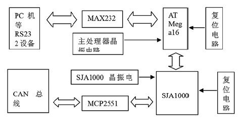
First, a brief description of CAN bus and RS232 protocol
As a multi-master serial communication bus, CAN's basic design specification requires high bit rate and high anti-electromagnetic interference performance, and it can detect any errors generated on the communication bus. When the signal transmission distance is up to 10km, CAN can still provide data transmission rate of up to 5kbit/s. Table 1 shows the maximum transmission distance between any two nodes on the CAN bus.
Correspondence with its bit rate.
It can be seen that the CAN bus is an excellent serial bus in terms of real-time, adaptability, flexibility, and reliability. When the two serial devices are far apart and cannot be directly connected by RS-232, RS-232 can be converted to CAN, and the serial port device network interconnection can be realized through the CAN bus.

Table 1 Maximum distance between any two sections of the CAN bus system
Both RS-232 and CAN are very different in level and frame format. The specific performance is as follows: RS-232 standard level ± (3V ~ 15V). The CAN signal is transmitted using differential voltage. The two signal lines are called “CAN_H†and “CAM_Lâ€. The static time is about 2.5V. The frame format of the RS-232 serial port is: one start bit, eight data bits. , one programmable ninth bit, one stop bit. The data frame format of CAN is: frame information + ID + data.
Second, CAN bus to RS232 overall design
CAN bus to 2 3 2 interface hardware circuit, mainly selected MAX232, ATMega16, SJAl000 and MCP2551 design.
Its principle block diagram is shown in Figure 1.

Third, the converter hardware design
3.1 main controller design
The main controller selects ATMEL16's ATMega16 as the main processor. The chip is a low-voltage, high-performance microcontroller with EEPROM and random access data memory (RAM), compatible with standard MCS-51 command system. .
ATMega16 has 44 pins, 32 external bidirectional I/0 ports, and includes 3 external interrupt ports, 2 8-bit and 1 16-bit programmable timing counters, and 1 full-duplex serial communication port. ATMega16 It can be programmed in the usual way or online. ATMega16's 4-pin reset circuit, active low; 9,10 pin connected to MAX232 data receiving/transmitting terminal; PD port connected to SJAl000 control terminal; 7,8 pin connected to crystal oscillator circuit; PB port connected to SJAl000 Use the address / data bus.
3.2 MAx232 circuit design
The MAX232 chip was chosen as the level shifter for the RS232 and CAN buses. The MAX232 is a level-shifting driver that provides TTL and RS232 level conversion. Its 13 and 14 feet are connected to the 2, 3 pins of the 232 interface; the 11 and 12 pins are connected to the receiving and transmitting ends of the MCU. 

SFP (Small Form-factor Pluggable) can be simply understood as an upgraded version of GBIC. GBIC (abbreviation for Gigabit Interface Converter) is an interface device that converts gigabit electrical signals into optical signals. GBIC is designed to be hot-swappable. GBIC is an interchangeable product that meets international standards. Gigabit switches designed with GBIC interfaces have a large market share due to flexible interchangeability.
GBIC modules are divided into two categories: one is the GBIC module used by ordinary cascade to realize the ordinary connection with other switches; the other is the stack dedicated GBIC module to realize the redundant connection with other switches.
GBIC was basically replaced by SFP for the following reasons:
SFP (Small Form-factor Pluggables) can be simply understood as an upgraded version of GBIC.
SFP module (the volume is reduced by half compared to the GBIC module, and the number of ports can be more than doubled on the same panel.
Because the SFP module is basically the same as GBIC in function, it is also called Mini-GBIC (Mini-GBIC) by some switch manufacturers.
The SFP module further compresses the size and power consumption by putting CDR and electric dispersion compensation outside the module. Used in optical communication applications in telecommunications and data communications. SFP connects the motherboard and optical fiber or UTP cable of network equipment such as switches, routers and other equipment. SFP is an industrial specification supported by some fiber optic component providers.
SFP supports SONET, Gigabit Ethernet, Fiber Channel and some other communication standards. This standard is extended to SFP+, which can support 10.0 Gbit/s transmission rate, including 8 gigabit Fibre Channel and 10GbE. Introduced the optical fiber and copper core version of the SFP+ module version. Compared with the Xenpak, X2 or XFP version of the module, the SFP+ module keeps part of the circuit on the main board instead of the module.
Sfp Module,Epon Sfp,Gpon Sfp
Shenzhen GL-COM Technology CO.,LTD. , https://www.szglcom.com
