
AUTOSAR is a layered architecture of automotive electronics embedded software jointly launched by global automotive OEMs and suppliers. The layered architecture consists of a microcontroller abstraction layer, an ECU abstraction layer, a service layer, a runtime environment (RTE), and an application layer. The front layer is collectively referred to as a base software (BSW).
This article refers to the address: http://
The communication of each layer of AUTOSAR software is realized through the interface of the class, which is the standard interface, the AUTOSAR interface and the standard AUTOSAR interface. Among them, the standard interface is used for communication between the various modules of the BSW, which has been defined in C language, such as void Adc_Init(const Adc_ConfigType* ConfigPtr). The AUTOSAR interface is used for communication between software components (SW-C) or for communication between software components and ECU firmware (IO hardware abstraction, complex device drivers). Such interface names are prefixed with 'Rte_'. The standard AUTOSAR interface is used for software component access to AUTOSAR services. Depending on this layered architecture and interface definition, AUTOSR significantly improves the reusability of automotive electronics embedded software - the higher the level, the more reusable. It is worth noting that:
* The microcontroller abstraction layer has the lowest level and is replaced with the replacement of the microcontroller;
* Although the RTE level is only lower than the application layer, it is responsible for the bridge between the application layer and the BSW, and has the highest coupling with the hardware, and has no reusability;
* The application layer (except for the sensor and actuator-related software components) is completely independent of the hardware and has absolute reusability.
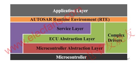
Figure 1 AUTOSAR layered architecture
*
Introduction to car diagnosis
Currently, OEMs and suppliers use a combination of online diagnostics and offline diagnostics. Online diagnostics enable self-diagnosis through the internal hardware and software of the ECU. During the execution of the vehicle, the self-diagnostic system instantly monitors the operational status of the various components of the electronic control system, thereby detecting faults in the electronic control system. On the one hand, the self-diagnosis system warns the driver of the detected fault in a certain way (such as an alarm indicator), and stores the fault code and related data in the ECU memory on the other hand. Offline diagnosis The diagnostic information is read by an external diagnostic device to read the corresponding diagnostic information. The key to achieving offline diagnostics is how to implement the communication mechanism and diagnostic service between the diagnostic device and the ECU, ie the diagnostic protocol.
At present, the diagnostic protocol standards are mainly divided into two systems: ISO and SAE. The United States uses the SAE standard system, and most countries, including China, use the ISO standard system. In the passenger vehicle sector, OEMs are moving from custom diagnostic protocols to ISO standards. In the commercial vehicle sector, OEMs follow the SAE diagnostics, and European OEMs have added ISO diagnostics based on this. Table 1 lists some of the ISO and SAE standard controls.
AUTOSAR CAN diagnostic implementation
1) Diagnostic services
Currently, the AUTOSAR V3.1 diagnostics section supports 9 OBD services (as shown in Table 2) and 14 UDS services (as shown in Table 3).
According to Table 2 and Table 3, AUTOSAR does not support 0x05 service in OBD (requesting oxygen sensor monitoring results), because the 0x05 service based on CAN line is implemented in 0x06. 0x28 (communication control), 0x34 (program download), 0x35 (program upload), 0x36 (data transfer), and 0x37 (request for transfer) services in UDS are not supported, and the 0x10 service does not support both programming sessions and extended sessions. Seed function. These services are mainly used for ECU reprogramming, so AUTOSAR does not support bootloaders.
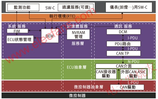
Figure 2 AUTOSAR CAN diagnostic related module
Although AUTOSAR does not currently support the above services, it does not restrict developers from extending it.
2) Software architecture
The modules related to diagnosis in the AUTOAR architecture are shown in Figure 2.
The role of the FIM module is to enable or disable functional entities inside the software component based on the event status reported by the DEM (Diagnostic Event Manager). The PDU Router (Protocol Data Unit Router) module is only responsible for forwarding I_PDUs (Interactive Layer Protocol Data Units) between DCM (Diagnostic Communication Manager) and CAN TP (CAN Transport Layer) without any modification to the data. The CAN Interface module, the CAN Driver module, and the CAN Transceiver module are responsible for the transmission of the L_PDU (Data Link Layer Protocol Data Unit).
DEM, DCM and CAN TP are core modules related to diagnostics in the AUTOSAR architecture.
3) DCM
The DCM module complies with ISO 14229-1, ISO 15031-5, ISO 15765-4 and SAE J1979 standards and can handle 0x10, 0x27 and 0x3E services directly. When receiving an OBD service or other UDS service supported by AUTOSAR, it responds by means of an interface provided by DEM, software components or other BSW modules.
AUTOSAR recommends using one function module to form DCM, which are DSL (Diagnostic Session Layer), DSD (Diagnostic Service Dispatcher) and DSP (Diagnostic Service Processing). The DSL is responsible for processing the diagnostic request sent by the PDU Router, managing the session layer and application layer timing parameters, and handling the switching of the session state. The DSD is responsible for forwarding the diagnostic request sent by the DSL to the DSP, and transmitting the diagnostic response message sent by the DSP to the DSL. The DSP is responsible for analyzing the received diagnostic request message, checking its message format and its requested sub-functions. Only when the service identifier, sub-function, and packet format of the diagnostic request packet are satisfied, the DSP processes the received request packet and organizes the processing result into a diagnostic response packet to be sent to the PDU Router. .
4) DEM
The DCM module follows the same standards as DCM and is responsible for directly handling DTC-related services, such as 0x19 services in UDS (response messages are sent by DCM). When the Monitor Function in the software component detects a fault or the BSW module detects a fault, it will notify the DEM module to process and store the 'diagnostic event' (identified by the Event ID). If the fault is diagnosed, the interface provided by the NVRAM Manager (non-volatile memory manager) accesses it to the non-volatile memory and notifies the application layer to indicate the fault. The state diagram of DEM is shown in Figure 3:

Figure 3 DEM state diagram
5) CAN TP module
Follow the ISO 15765-2 standard. Responsible for the addressing, unpacking and packing of diagnostic messages, and the management of network layer timing parameters. Therefore, the module transmits N_PDU (network layer protocol data unit) downward.
in conclusion
First, due to strict stratification, in addition to CAN Driver and CAN Transceiver modules relying on hardware, AUTOSAR and diagnostic-related modules are almost completely independent of hardware. Diagnostic code developed according to this architecture can get rid of hardware constraints and have maximum reusability.
Second, AUTOSAR does not currently support SAE J1939.
Dijon, temporarily can not directly use the AUTOSAR software architecture for the development of the Bootloder program.
In summary, the AUTOSAR standard is still in the stage of development and improvement. However, with the intensification of the development of automotive ECU software, the difficulty of development is increasing, and the development cycle is shortening. AUTOSAR will become an inevitable trend.
The PUS series is one low weight ultra-thin compact size, universal AC input 100-240V 50/60Hz constant voltage smart led driver provides dc output 12 volt 24 volt single output wattage 20W 40W 60W 90W with 5 years warranty. The PUS series smart mirror anti-fog led driver provides protections for short circuit, over load, over voltage and over temperature. The display cabinet lighting transformers use low profile plastic housing, featuring built-in PFC function more than 0.95 and flicker free outstanding led power performance. The led driver have heating wire and anti-fog control function, IP20/IP65/Nema 3R rated for dry, damp and wet (optional) locations. The bathroom led driver is UL CE Class 2 SAA RoHS CCC Listed and SELV style enclosures, defogger control relay integration make the power solutions perfectly suitable for bathroom lighting, display cabinet, advertising lighting, Anti-fog mirror, Freezer lighting, Kitchen cabinet,wardrobe and stage lightings. Label, screw cover color, LOGO and design solution accept customization.
power supply transformer 12v,transformer for lights,slim power supply,transformer adapter converter,12 volt dc driver
Shenzhenshi Zhenhuan Electronic Co., Ltd , https://www.szzhpower.com