
Circuit Operation Principle The automatic hand dryer circuit consists of a power supply circuit, an infrared transmitting circuit, an infrared receiving amplifying circuit, a detecting circuit and a control circuit, as shown in Figure 9-125.
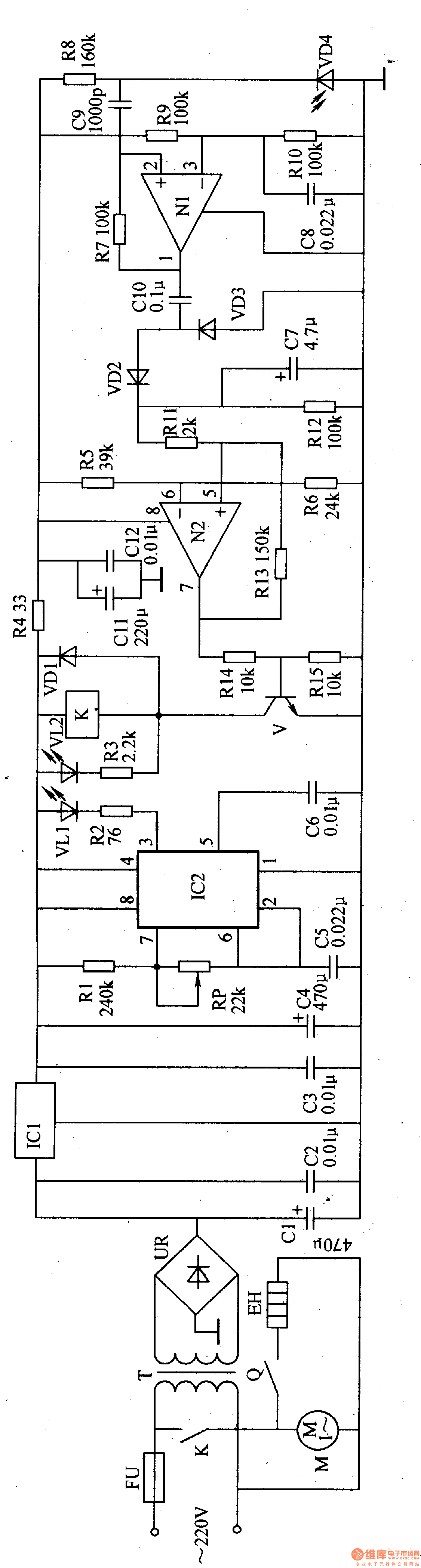
The power circuit is composed of a fuse FU, a power transformer T, a rectifier bridge stack UR, a filter capacitor Cl-C4, and a three-terminal voltage regulator integrated circuit IC1.
The infrared transmitting circuit is composed of a time base integrated circuit IC2, resistors R1 and R2, capacitors C5 and C6, a potentiometer RP and an infrared light emitting diode VLl.
The infrared receiving and amplifying circuit is composed of an infrared photodiode VD4, a resistor R7-R10, a capacitor C8, a Cg, and an N1 inside the operational amplifier integrated circuit IC3 (N1, N2).
The detector circuit consists of capacitors ClO, C7 and diodes VD2, VD3.
The control circuit is composed of resistors R3-R6, R11-R15, 1C3 internal amplifier N2, capacitor C11, Cl2, diode VD1, transistor V, relay K and work indicating light-emitting diode VL2. Among them, V, Rl4, Rl5, VDl and K constitute a relay driving circuit, and N2 and R5, R6 and Rll-R13 constitute a comparative amplifying circuit.
M is a fan motor and EH is an electric heater.
Turn on the power, AC 220V voltage after T step-down, UR rectification, Cl filtering and ICl voltage regulation, provide +l2V working voltage for infrared transmitting circuit and relay driving circuit. The +l2V voltage is also filtered by R4 and filtered by C11 and Cl2, and is used as the working power source for IC3 and infrared receiving circuits.
After the oscillator consisting of IC2 and Rl, RP, C5, and C6 is energized, the VLl is driven to emit modulated infrared light. Normally, VD4 can not receive the infrared light emitted by VLl, the operational amplifier N2 outputs a low level, V is in the off state, K does not pull in, VL2 does not emit light, and M and EH do not work.
When the hand is reached to the air outlet, the VD4 receives the infrared light reflected by the hand and converts it into an electrical signal. The electrical signal is amplified by the operational amplifier N1 and the detection circuit is double-voltage detected and processed to become a positive DC. The voltage signal is applied to the non-inverting input terminal of N2, so that N2 outputs a high level, V saturation is turned on, VL2 is turned on, K is energized, K is normally open contact is turned on, M and EH are energized, and the air outlet is Blow out hot air and dry your hands.
When the hand leaves the air outlet, VD4 can not receive the infrared signal, Nl has no signal output, and C7 discharges through Rl2, so that N2 maintains the output high level. When the C7 discharge ends, N2 outputs a low level, which causes V to turn off, VL2 to go out, K to release, and EH and M to stop working.
Component selection
Rl-R3 and R5-Rl5 both use 1/4W metal film resistors; R4 uses 1/2W metal film resistors.
The RP uses a small organic solid potentiometer or a variable resistor.
Cl, C4 and C11 are selected from aluminum electrolytic capacitors with a withstand voltage of 25V; C2, C3, C5, C6, C8 and Cl2 are selected from monolithic capacitors or polyester capacitors; C7 is selected from aluminum electrolytic capacitors with a withstand voltage of 16V; C9 and ClO uses high frequency ceramic capacitors or glass glaze capacitors.
VD1 selects 1N4007 type silicon rectifier diode; VD2 and VD3 select lN4148 type silicon switch diode; VD4 selects PH302 or RPM-30IB type infrared photodiode.
VL1 selects HG302 or HG303, HG4lO, SE303 type infrared light-emitting diodes; VL2 selects d5mm green high-brightness light-emitting diodes.
UR selects the rectifier bridge stack of lA and 5OV.
V selects S8050 type silicon NPN transistor.
ICl selects LM7812 type three-terminal voltage regulator integrated circuit; IC2 selects NE555 type time base integrated circuit; IC3 selects LM358 type double operational amplifier integrated circuit.
K selects JRX-l3F type l2V DC relay.
T selects 3-5W, the secondary voltage is l5V power transformer.
M selects 10-20W, 220V small fan motor.
EH uses about 2OOW of heating wire.
Shenzhen Happybate Trading Co.,LTD , https://www.szhappybateprojector.com